Transcription of Concrete Step Barrier Design Guidance …
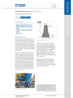
1 Concrete step Barrier Design GuidanceCONCRETE step Barrier Design GuidancePrepared for Britpave by ArupDS/CSB/516 CSB: Conforming to BS EN 1317 DRAWINGSCSB/002 Design Guidance NotesThe CSB products illustrated on the Britpave drawings and described in these data sheets conform to BS EN 1317. Design and construction outside the specification and Design provided in the current Britpave drawings will result in a non-compliant standards and test requirements for road vehicle restraint systems are specified in BS EN 1317-2 . The requirements for the tests and the achieved values are summarised in Table 1 below.
2 Britpave Surface-Mounted Concrete step Barrier was tested at MIRA in the UK in April 2006. This product is discussed on Data Sheet DS/ CSB was tested in 1995 at in France and was subjected to both a car and bus test resultsTest TypeCarBusCarBusVehicle Mass(kg)900 40013 000 40087012 650 Vehicle Speed(km / h) angle ( )20202021 There are three main criteria within BS EN 1317: Containment level maximum vehicle impact without failure of the Barrier Impact severity level the effect of impact on the occupants Deformation of restraint system the dynamic envelope of the Barrier or vehicleContainment LevelCSB has containment class H2.
3 Vehicle tests require the Barrier to successfully contain vehicles up to 13 tonnes. The results from the test demonstrate that CSB can contain and redirect cars and buses. Although CSB can contain a 13 tonne bus, it can also minimize injuries to the occupants of small vehicles, thus ensuring safety for all kinds of Severity LevelThe effect of impact on occupants is more severe for a small vehicle than for larger vehicles. The impact severity level (Table 2) of the system has been assessed, in accordance with BS EN 1317, on three measures for the TB11 (car) test: ASI: Acceleration severity index THIV: Theoretical head impact velocity PHD.
4 Post-impact head decelerationImpact severity level class ASI valueTHIV & PHD valuesA THIV 33 km/h PHD 20 gB that provide lower Impact Severity Levels offer a greater level of safety for the occupants of an errant , TD 192 requires that the impact severity level for safety barriers should not exceed Class 1317requirementsLIER testImpact severity levelsASIA, B or km/hPHD20 gContainment levelH2H2 Results for CSB are significantly better than those achieved for VCB. Britpave has conducted a study into ASI and impact with CSB. Further information is available on : Conforming to BS EN 1317 CSB: Conforming to BS EN 1317DS/CSB/516 THE KNOWLEDGEI ssue No 03 Issue Date July 09 CSB/1000 Table 1: Test parameters for embedded CSBT able 2: Impact severity levelsTable 3: Test requirements & results for CSB1 BS EN 1317-2.
5 Road Restraint Systems Performance classes, impact test acceptance criteria and test methods for safety barriers2 TD 19 Requirement for Road Restraint SystemsE-mail 01276 33160 Website Atrium Court, The Ring, Bracknell, Berkshire, RG12 1 BWCONCRETE step Barrier Design GuidancePrepared for Britpave by ArupDeformation of Restraint System The deformation of the restraint system during impact tests is characterised by dynamic deflection and the working width. CSB is a rigid safety Barrier system; the test shows that dynamic deflection is zero in both the car and bus tests, while there is a working width of W1 and W2 respectively.
6 Table 4 shows the relationship between levels and centre of gravity of the test vehicle does not cross the centreline of the deformed system, eliminating the catastrophic crossover accident. The Barrier contains and redirects the vehicle without structural damage to the principle longitudinal elements of the system. Working width(m)Classes of working widthW CSB is subjected to a TB51 test (Figure 1), CSB contains the vehicle and re-directs it along the face of Barrier in the same direction as the traffic flow (Figure 2).Minimal DamageUnder test conditions, CSB sustains minimal damage on impact (Figure 3).
7 The Barrier continues to be serviceable and provide containment, even after the TB51 contrasts with deformable steel safety Barrier products, which are severely damaged during the TB51 test (Figure 4) and require replacement even after the TB11 car steel safety barriers are unusable following impact and require replacement, leading to high maintenance costs, with disruption to the road does not need repair, resulting in low maintenance costs, and lower risk to maintenance CSB: Conforming to BS EN 1317DS/CSB/516 CSB: Conforming to BS EN 1317 THE KNOWLEDGEI ssue No 03 Issue Date July 09 Figure 1TB51 test showing 13t bus at 70kphapproaching CSB at 20 Table 4: Levels of working width reproduced from BS EN 1317 Figure 2TB51 test showing 13t bus after impact with CSBA deformable steel safety Barrier following TB51 testFigure 3 CSB following TB51 testFigure 4