Transcription of CONDUCTIVE POLYMER ALUMINUM SOLID ELECTROLYTIC …
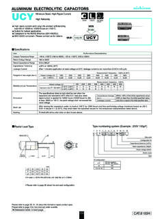
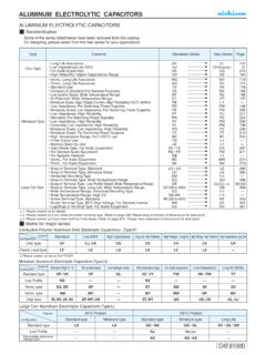
1 POLYMER ALUMINUM SOLID ELECTROLYTIC CAPACITORSCS seriesChip Type, Long Life AssuranceSpecificationsTemperature Characteristics( Ratio)Category Temperature RangeRated Voltage RangeRated Capacitance RangeCapacitance ToleranceTangent of loss angle (tan )ESR (1)Leakage Current (2)Performance CharacteristicsItem 55 to +105 C4 to 16V22 to 560 F 20% at 120Hz, 20 CLess than or equal to the specified value at 120Hz, 20 CLess than or equal to the specified value at 100kHz, 20 CLess than or equal to the specified value . After 2 minutes' application of rated voltage at 20 CZ+105 C / Z+20 C (100kHz)Z 55 C / Z+20 C Heat(Steady State)
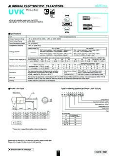
2 Resistance to Soldering HeatMarkingThe specifications listed at right shall be met when the capacitors are restored to 20 C after the rated voltage is applied for 5000 hours at 105 specifications listed at right shall be met when the capacitors are restored to 20 C after the rated voltage is applied for 1000 hours at 60 C, 90% soldering the capacitor under the soldering conditions prescribed here, the capacitor shall meet the specifications listed at right, provided that it's temperature profile is measured at the capacitor top and the shall be done at 150 to 200 C and for 60 to 180 duration for over +230 C temperature at capacitor surface shall not exceed 60 the case of peak temp, less than 250 C, reflow soldering shall be two times the case of peak temp, less than 260 C, reflow soldering shall be for solder temperature profile shall be made at the capacitor top and the blue print on the case topCapacitance changetan Leakage current (2)ESR (1)Within 20% of the initial capacitance value (3)
3 150% or less than the initial specified value150% or less than the initial specified valueLess than or equal to the initial specified valueCapacitance changetan Leakage current (2)ESR (1)Within 20% of the initial capacitance value (3)150% or less than the initial specified value150% or less than the initial specified valueLess than or equal to the initial specified valueCapacitance changetan Leakage current (2)ESR (1)Within 10% of the initial capacitance value (3)130% or less than the initial specified value130% or less than the initial specified valueLess than or equal to the initial specified valueLoad life of 5000 hours at 105 type : Lead free reflow soldering condition at 260 C peak to the RoHS directive (2011/65/EU).
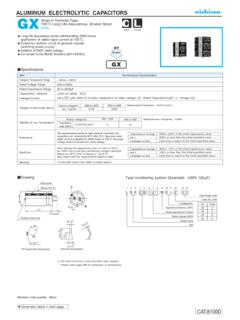
4 1 ESR should be measured at both of the terminal ends closest where the terminals protrude through the plastic Conditioning : If any doubt arises, measure the leakage current after the voltage treatment of applying DC rated voltage continuously to the capacitor for 120 minutes at 105 Initial value : The value before test of examination of resistance to codeSize codeCapacitance tolerance ( 20%)Rated capacitance (220 F)Rated voltage ( )Series D ( )Plastic platformLot + numbering system (Example : 220 F) Voltage V 4 10 16 Code g j A CSize DLABCEH 5 to to 8 to (mm) Dimension table in next POLYMER ALUMINUM SOLID ELECTROLYTIC CAPACITORSCS seriesStandard Ratings Taping specifications are given in page 23.
5 Recommended land size, soldering by reflow are given in page 18, 19. Please refer to page 3 for the minimum order ripple current (mArms) at 105 C 100kHzRated Capacitance( F)Rated Voltage(V)(code)Surge Voltage (V)Leakage Current( A)ESR (m )(at 100kHz 20 C)Rated Ripple(mArms)tan Part NumberCase Size D L (mm)4(0G)16(1C)10(1A) (0J) 6 8 78 75 65 6 6 6 8 78 75 6 5 6 8 78 75 65 6 6 8 78 7 No marked, 1 will be put at 12th digit of type numbering system.: In this case, 9 will be put at 12th digit of type numbering system.