Transcription of CONDUCTIVE POLYMER ALUMINUM SOLID ELECTROLYTIC …
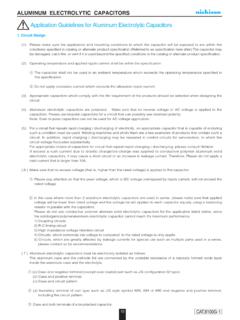
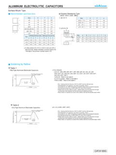
1 CONDUCTIVE POLYMER ALUMINUM SOLID ELECTROLYTIC capacitors . CJ. Chip Type, Low ESR, Higher Capacitance series CK. Low ESR, Higher Capacitance, High ripple current. Low ESR. Load life of 2000 hours at 105 C. SMD type : Lead free reflow soldering condition at 260 C peak correspondence. Compliant to the RoHS directive (2011/65/EU). CJ. Low ESR. Higher Capacitance, CF. Specifications Item Performance Characteristics Category Temperature Range 55 to +105 C. Rated Voltage Range to 16V. Rated Capacitance Range 33 to 2700 F. Capacitance Tolerance 20% at 120Hz, 20 C. Tangent of loss angle (tan ) Less than or equal to the specified value at 120Hz, 20 C. ESR ( 1) Less than or equal to the specified value at 100kHz, 20 C. Leakage Current ( 2) Less than or equal to the specified value.
2 After 2 minutes' application of rated voltage at 20 C. Temperature Characteristics Z+105 C / Z+20 C (100kHz). ( Ratio) Z 55 C / Z+20 C Capacitance change Within 20% of the initial capacitance value ( 3). The specifications listed at right shall be met when the tan 150% or less than the initial specified value Endurance capacitors are restored to 20 C after the rated voltage is ESR ( 1) 150% or less than the initial specified value applied for 2000 hours at 105 C. Leakage current ( 2) Less than or equal to the initial specified value Capacitance change Within 20% of the initial capacitance value ( 3). Damp Heat The specifications listed at right shall be met when the tan 150% or less than the initial specified value capacitors are restored to 20 C after the rated voltage is ESR ( 1).
3 (Steady State) 150% or less than the initial specified value applied for 1000 hours at 60 C, 90% RH. Leakage current ( 2) Less than or equal to the initial specified value After soldering the capacitor under the soldering conditions prescribed here, the capacitor shall meet the specifications listed at Capacitance change Within 10% of the initial capacitance value ( 3). right, provided that it's temperature profile is measured at the tan 130% or less than the initial specified value capacitor top and the terminal. ESR ( 1) 130% or less than the initial specified value Pre-heating shall be done at 150 to 200 C and for 60 to 180 sec. Leakage current ( 2) Less than or equal to the initial specified value Resistance to The duration for over +230 C temperature at capacitor surface shall not exceed 60 seconds.
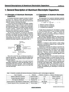
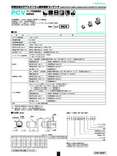
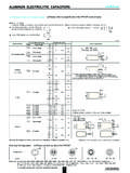
4 Soldering Heat In the case of peak temp, less than 250 C, reflow soldering shall be two times maximum. In the case of peak temp, less than 260 C, reflow soldering shall be once. Measurement for solder temperature profile shall be made at the capacitor top and the terminal. Marking Navy blue print on the case top 1 ESR should be measured at both of the terminal ends closest where the terminals protrude through the plastic platform. 2 Conditioning : If any doubt arises, measure the leakage current after the voltage treatment of applying DC rated voltage continuously to the capacitor for 120. minutes at 105 C. 3 Initial value : The value before test of examination of resistance to soldering. Dimensions Type numbering system (Example : 220 F). 1 2 3 4 5 6 7 8 9 10 11 12 13 14.
5 Positive Plastic platform PC J 0 J 2 2 1 MC L 1 GS. MAX. Capacitance Lot No. MAX. C Taping code Size code Configuration D B 220. 841. A Capacitance tolerance ( 20%). CJ. E. j Rated capacitance (220 F). L + Rated voltage ( ). Series Voltage ( ) Negative Series name H. Type (mm). Size 5 6L 6L 8L 8 7L 8 8L 8 10L 8 12L 10 8L 10 10L 10 D L A B Voltage C V 4 10 16. E H to to to to to to to to to to Code e g j A C. Dimension table in next page. CONDUCTIVE POLYMER ALUMINUM SOLID ELECTROLYTIC capacitors . CJ series Standard Ratings Rated Voltage Surge Voltage Rated Capacitance Case Size Leakage Current ESR (m ) Rated Ripple tan Part Number (V)(code) (V) ( F) D L (mm) ( A) (at 100kHz 20 C) (mArms). 180 5 6 90 21 2670 PCJ0E181 MCL1GS. 390 6 195 15 3400 PCJ0E391 MCL1GS.
6 470 8 235 13 3600 PCJ0E471 MCL1GS. 560 8 280 13 3600 PCJ0E561 MCL4GS. 560 8 7 280 13 4100 PCJ0E561 MCL1GS. 680 8 7 340 13 4100 PCJ0E681 MCL1GS. 820 8 8 410 12 4260 PCJ0E821 MCL6GS. 820 8 12 410 9 5400 PCJ0E821 MCL1GS. (0E). 1000 8 8 500 12 4260 PCJ0E102 MCL1GS. 1200 10 8 600 13 4800 PCJ0E122 MCL1GS. 1500 8 10 750 10 5220 PCJ0E152 MCL6GS. 1500 8 12 750 9 5400 PCJ0E152 MCL1GS. 2200 10 10 1100 10 5500 PCJ0E222 MCL1GS. 2700 10 1350 9 5800 PCJ0E272 MCL1GS. 100 5 6 80 22 2610 PCJ0G101 MCL1GS. 150 5 6 120 22 2610 PCJ0G151 MCL1GS. 270 6 216 15 3200 PCJ0G271 MCL1GS. 330 6 264 15 3300 PCJ0G331 MCL1GS. 390 8 312 14 3470 PCJ0G391 MCL1GS. 470 8 7 376 14 3950 PCJ0G471 MCL1GS. 560 8 7 448 14 4000 PCJ0G561 MCL1GS. 560 8 12 448 9 5200 PCJ0G561 MCL9GS. 680 8 8 544 13 3950 PCJ0G681 MCL1GS.
7 4 1000 8 10 800 10 5220 PCJ0G102 MCL4GS. (0G) 1000 10 8 800 13 4300 PCJ0G102 MCL1GS. 1200 8 12 960 9 5400 PCJ0G122 MCL1GS. 1200 10 10 960 10 5500 PCJ0G122 MCL6GS. 1500 8 12 1200 9 5200 PCJ0G152 MCL4GS. 1500 10 10 1200 10 5500 PCJ0G152 MCL1GS. 1800 10 10 1440 10 5500 PCJ0G182 MCL1GS. 1800 10 1440 9 5600 PCJ0G182 MCL9GS. 2200 10 1760 9 5700 PCJ0G222 MCL1GS. 100 5 6 126 24 2500 PCJ0J101 MCL1GS. 120 5 6 151 24 2500 PCJ0J121 MCL1GS. 220 6 277 15 3200 PCJ0J221 MCL1GS. 270 8 340 14 3470 PCJ0J271 MCL1GS. 330 8 416 14 3470 PCJ0J331 MCL4GS. 330 8 7 416 14 3950 PCJ0J331 MCL1GS. 390 8 7 491 14 3950 PCJ0J391 MCL1GS. 470 8 8 592 13 3950 PCJ0J471 MCL1GS. (0J). 820 8 10 1033 12 4770 PCJ0J821 MCL6GS. 820 8 12 1033 10 5150 PCJ0J821 MCL4GS. 820 10 8 1033 13 4500 PCJ0J821 MCL1GS.
8 1200 10 10 1512 12 5025 PCJ0J122 MCL1GS. 1500 10 10 1890 12 5025 PCJ0J152 MCL1GS. 1500 10 1890 10 5500 PCJ0J152 MCL9GS. 1800 10 2268 11 5200 PCJ0J182 MCL1GS. 47 5 6 94 28 2310 PCJ1A470 MCL1GS. 56 5 6 112 28 2310 PCJ1A560 MCL1GS. 68 5 6 136 28 2310 PCJ1A680 MCL1GS. 120 6 240 25 2530 PCJ1A121 MCL1GS. 150 8 300 21 2880 PCJ1A151 MCL1GS. 10. 220 8 7 440 21 3220 PCJ1A221 MCL1GS. (1A). 270 8 7 540 21 3220 PCJ1A271 MCL1GS. 330 8 8 660 19 3390 PCJ1A331 MCL1GS. 390 8 10 780 17 4000 PCJ1A391 MCL1GS. 470 10 8 940 19 3800 PCJ1A471 MCL1GS. 680 10 10 1360 13 4820 PCJ1A681 MCL1GS. 33 5 6 105 35 2070 PCJ1C330 MCL1GS. 39 5 6 125 35 2070 PCJ1C390 MCL1GS. 68 6 217 28 2390 PCJ1C680 MCL1GS. 82 8 262 24 2700 PCJ1C820 MCL1GS. 100 8 320 24 2700 PCJ1C101 MCL4GS. 100 8 7 320 24 3010 PCJ1C101 MCL1GS.
9 16. 120 8 7 384 24 3010 PCJ1C121 MCL1GS. (1C). 150 8 8 480 22 3150 PCJ1C151 MCL1GS. 180 8 10 576 18 3890 PCJ1C181 MCL1GS. 220 8 10 704 18 3890 PCJ1C221 MCL4GS. 220 10 8 704 22 3450 PCJ1C221 MCL1GS. 270 8 12 864 16 4070 PCJ1C271 MCL1GS. 330 10 10 1056 16 4350 PCJ1C331 MCL1GS. Rated ripple current (mArms) at 105 C 100kHz Taping specifications are given in page 23. No marked, 1 will be put at 12th digit of type numbering system. Recommended land size, soldering by reflow are given in page 18, 19. : In this case, 4 will be put at 12th digit of type numbering system. Please refer to page 3 for the minimum order quantity. : In this case, 6 will be put at 12th digit of type numbering system. : In this case, 9 will be put at 12th digit of type numbering system.