Transcription of Connecting Your Receiver to the Antenna - DXing.com
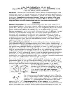
1 1 TECHNOTE No. 3 Joe Carr's Radio Tech-NotesConnecting Your Receiver to the AntennaJoseph J. CarrUniversal Radio, Americana ParkwayReynoldsburg, Ohio 430682 Connecting Your Receiver to the AntennaJoseph J. CarrThis paper shows you how to make the connection from the Antenna to yourreceiver. Although there may be other types of connectors than those covered, theconnections discussed below represent the largest percentage. But first, let's take a look atthe different types of downlead or transmission line used between radio antennas LinesThe piece of wire that runs between the Antenna and the Receiver is called thedownlead, or the transmission line. The simplest form of downlead is a single piece ofinsulated #16 AWG or #14 AWG wire soldered at one end to one end of the Antenna , and atthe other end is fastened to the Antenna input of the Receiver . Other forms of transmissionline are a little more popular form of transmission line is 300-ohm twin-lead (Fig.)
2 1A). This is thetype of line once used extensively for television Receiver antennas. This type of transmissionline is often used with antennas such as the folded dipole; it consists of two insulatedconductors, about 1 cm apart, molded in a plastic or rubber-like material that keeps the twoconductors separated by a constant 1AA close cousin of 300-ohm line is the 450-ohm twin-lead shown in Fig. 1B. It can beidentified by the fact that it is about twice the width of 300-ohm line, and usually hassections cut out of the insulation to reduce loss at UHF. This type of line is often used withantennas such as the G5RV, or other antennas with a high impedance balanced feed. It isalso used occasionally with 600-ohm feedpoint antennas because the VSWR produced(600/450 = :1) by the mismatch is quite 1B3 Less popular, but none the less useful (when needed) is the parallel open-feedertransmission line in Fig.
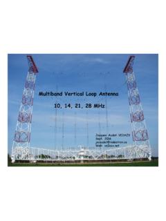
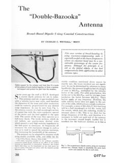
3 1C. According to an Irish amateur radio operator I know, this line ismore popular in Europe than in the USA. This line consists of two conductors separated byinsulating spreaders. The spreaders are made of ceramic, plastic, nylon or some otherinsulating material. When purchased commercially, this line is usually called "ladder line,"and is available in characteristic impedances from about 400 to 800 ohms, with 600 ohmsbeing the most 1 CBy far, the most commonly used transmission line is coaxial cable (Fig. 2). Itconsists of two conductors that share a common axis (hence "co-axial"). This means thatthere is a center conductor that is at the center of a tubular outer conductor, usually calledthe "shield." An insulating material separates the two conductors (polyethylene, polyfoamand Teflon are used). An outer insulating sheath is also provided, and serves to protect theshield both electrically and from the 2 Receiver ConnectorsThere are several different forms of connection that might be used on a radioreceiver, and which to use depends partially on the type of transmission line used andpartially on the configuration of the Receiver Antenna 3 shows two popular Antenna connection schemes found on the rear panels ofshortwave receivers.
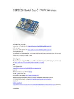
4 In Figs. 3, the Antenna connection consists of either two or three screws(two for unbalanced feedlines, three for balanced feedlines), one of which is for the cable end connectors needed for these connectors depend in part on the type ofdownlead or transmission line used. In fact, the "on-the-cheap" method is to not use aconnector at all. If a single wire downlead is used with a Receiver that has screw terminals,then some people just scrap about half inch of insulation away from the copper wire, andthen wrap the wire around the screw and tighten down. Others will use a two prong "spadelug" at the end of the single wire connectors in Figs. 3C and 3D are coaxial connectors. The version in Fig. 3C isthe SO-239 "UHF" connector, which is the most common, especially on shortwavereceivers. On some scanners, and a few shortwave receivers, however, the BNC form Receiver in Fig. 4 uses both types of connection (one for coaxial cable and onefor single-wire downleads).
5 The 50-ohm connection is for coaxial cable, while the HI-Zterminal to the right of the coaxial connector is for a high impedance feedline, which is afancy way of saying a single wire downlead. The ground terminal is also seen in Fig. 4. TheLOCAL-DX switch is used to connect a resistance in series with the Antenna lead in order toreduce the strength of overloading local 45 Connecting to Two- and Three-Terminal Antenna InputsFigure 5 shows three schemes for Connecting the Antenna feedline to screw-typeinput receivers. In Fig. 5A, the Receiver has only two Antenna terminals, one for the Antenna (A1) and the other for the ground or earth (G). If a single wire downlead is used, then it isconnected directly to the A1 terminal. Either scrapping the end, or use of a spade lug, asdescribed above, is sufficient. The ground wire is connected between the "G" terminal andwhat is usually called a "good ground" the case where the Receiver has a balanced Antenna input, and you wish to use asingle wire downlead (Fig.)
6 5B), then the connection is made to "A1" in the same manner asbefore. Similarly, the "G" terminal is grounded as before. What's different is the fact that the"A2" terminal is strapped to the "G" terminal with a short piece of hook-up wire (somereceivers use a small metal link that must be removed before a balanced Antenna is used).And speaking of balanced antennas, Fig. 5C shows the scheme for Connecting abalanced transmission line such as 300-ohm twin-lead to the Receiver . One conductor of theline goes to "A1" while the other conductor goes to "A2." The ground connection is some cases, you will have a Receiver as shown in Fig. 5, but want to use coaxialcable. One way to do this is to simply split the end of the coax, carefully separating the innerconductor and shield, and then Connecting them to the screw terminals. The inner conductorgoes to "A1," while the shield goes to either "G" or the shorted pair "A2-G.
7 " Not veryelegant, and certainly not recommended, but it works. A more elegant solution is to use aBALUN transformer, with either 1:1 or 4:1 impedance transformation (depending on theline type).6 Connecting to Coaxial InputsMost high-end and middle market receivers today are equipped with coaxialconnectors for the Antenna input. The task is to connect either a single wire downlead,coaxial cable or twin-lead to the coaxial input of the Receiver . Figure 7 shows one methodfor Connecting a single wire downlead to a coaxial connector. The cable end for thedownlead is a banana plug. It turns out that the standard banana plug has a spring-likeconstruction with a diameter that makes it a snug, but easy, fit in the SO-239 UHF coaxialconnector ( the mate to the PL-259).Fig. 7 The ideal situation is shown in Fig. 8: a coaxial input Receiver is mated with acoaxial cable from the Antenna lead. The PL-259 connector used as a cable end for the coaxis a direct mate with the SO-239 on the Receiver rear 8 This paper has discussed the various methods for Connecting the Antenna to thereceiver.
8 It is recommended that you also read the paper on good grounds, as well as variousbooks on radio antennas.