Transcription of CONTENTS
1 ICONTENTSC hapter 1. Getting 1-1 Mainboard 1-2 Mainboard 1-4 Chapter 2. Hardware 2-1 Quick Components 2-2 CPU (Central Processing Unit).. 2-2 Introduction to LGA 775 2-3 CPU & Cooler 2-7 Installing DDRII Modules .. 2-7 Power 2-8 ATX 24-Pin Power Connector: 2-8 ATX 12V Power Connector: 2-8 Back 2-11 Floppy Disk Drive Connector: FDD1 .. 2-11 ATA133 Hard Disk Connectors: IDE1 & 2-11 Serial ATA Connectors: SATA1, Password Clear: Power Connectors: CPU_FAN1, USB Connectors: JUSB1, Connector: SPDOUT1 ..2-14 Front Panel Audio Connector: Flash Write Protection: 1394 Connectors: Panel Connectors: JFP1/JFP2 ..2-15 Clear CMOS Jumper: Recovery: (Peripheral Component Interconnect) Express (Peripheral Component Interconnect) Interrupt Request 3. BIOS 3-1 Entering 3-2 Control 3-3 Getting 3-3iiGeneral Help <F1>.
2 3-3 The Main 3-4 Standard CMOS 3-6 Advanced BIOS 3-8 Advanced Chipset Management Optimized Supervisor/ User StartedGetting StartedChapter 1 Thank you for choosing the MS-7293 Series ( ) Micro ATX mainboard. The MS-7293 Seriesmainboards are based on VIA PT890 & VIA 8237 Achipsets for optimal system efficiency. Designed to fitthe advanced Intel Pentium 4 processor, themainboards deliver a high performance and profes-sional desktop platform Mainboard1-2 Processor Support- Supports Intel Pentium 4, Pentium D, Celeron Dand intel CoreTM 2 Duo processors in the LGA775 Supports 3/4 pin CPU Fan Pin-Header with Fan Speed Supports EIST Technology- Supports Hyper-Threading (HT) Technology- Supports Intel Dual Core TechnologySupported FSB- 533/800/1066 MHzChipset- North Bridge: VIA PT890- South Bridge.
3 VIA 8237 AMemory Support- DDRII 400/533 SDRAM (2GB Max)- 2 DDRII DIMMs (240pin / )LAN- Supports LAN 10/100 Fast Ethermet by VIA VT6103 LIEEE 1394- Chip integrated by VIA VT6308 Audio- Chip integrated by Realtek ALC888- Flexible 8-channel audio with jack sensing- Compliant with Azalia HD 2 ports (4 IDE channels).- Supports Ultra DMA 33/66/100/133 mode- Supports PIO, Bus Master operation modeSATA- 2 SATA ports- Supports 2 SATA Supports storage and data transfers at up to 150 MB/sFloppy- 1 floppy port- Supports 1 FDD with 360K, 720K, , and Specifications1-3 Getting StartedConnectorsBackpannel- 1 serial port (COM1)- 1 IEEE 1394 port- 4 USB Ports- 1 LAN jack- 6 flexible audio jacks- 1 SPDIF Out connectorOn-Board Pinheaders- 1 front Audio pinheader- 1 SPDIF-out pinheader- 1 IEEE 1394 pinheaders- 2 USB pinheaders- 1 front panel pinheader (JFP1)Slots- 1 PCI Express x16 slot- 1 PCI Express x1 slot- 2 PCI Support 5V PCI bus InterfaceForm Factor- Micro-ATX ( X )
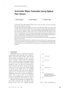
4 Mounting- 8 mounting holesMS-7293 Mainboard1-4MS-7293 M-ATX MainboardMainboard LayoutBATT+BIOSIDE 2 IDE 1 FDD 1 ATX 1 PCIE1_1 PCI2 PCI1 DIMM1 DIMM2 PCIE16_1 SYS_FAN1 CPU_FAN1 JBAT1 WinbondW83627 EHGJBR1 JPWD1 JUSB1J1394_1 SPDOUT1 JAUD1 Audio CodecVIAVT6103 LJUSB2 SATA1 SATA2 JWP1 JFP1 JPW1To p: L A N J a c kBottom: USB ports Top:1394 Bottom: USB ports T:M:B:Line-InLine-OutMicT: R S - O u tM:CS-OutB:SS-Out COM Port SPDIFOUT1 VIAVT8237A1394 ChipVIAPT8902-1 Hardware SetupHardware SetupChapter 2 This chapter provides you with the information abouthardware setup procedures. While doing the installa-tion, be careful in holding the components and followthe installation procedures. For some components, ifyou install in the wrong orientation, the componentswill not work a grounded wrist strap before handling computercomponents.
5 Static electricity may damage the Mainboard2-2 Quick Components GuideDDRII DIMMs, PanelI/O, , , Slots, , , , Slot, , , , , , , , , Slot, , , , , SetupCPU (Central Processing Unit)This mainboard supports Intel Pentium 4 processor in LGA 775 package. When youare installing the CPU, make sure to install the cooler to prevent you do not have the CPU cooler, contact your dealer to purchase and install thembefore turning on the the latest information about CPU, please visit Overheating will seriously damage the CPU and system. Always makesure the cooling fan can work properly to protect the CPU from Make sure that you apply an even layer of heat sink paste (or thermal tape)between the CPU and the heatsink to enhance heat While replacing the CPU, always turn off the ATX power supply or unplugthe power supply s power cord from the grounded outlet first to ensure thesafety of to LGA 775 CPUThe surface of LGA 775 to apply some siliconeheat transfer compound on it forbetter heat triangle is the Pin 1 indicatorThe pin-pad side of LGA triangle is the Pin 1 indicatorAlignment KeyAlignment KeyMS-7293 Mainboard2-42.
6 Remove the cap from lever hingeside (as the arrow shows).1. The CPU has a plastic cap on it toprotect the contact from you install the CPU, alwayscover it to protect the socket The pins of socket & Cooler InstallationWhen you are installing the CPU, make sure the CPU has a cooler at-tached on the top to prevent overheating. If you do not have the cooler, contactyour dealer to purchase and install them before turning on the computer. Meanwhile,do not forget to apply some silicon heat transfer compound on CPU before installingthe heat sink/cooler fan for better heat the steps below to install the CPU & cooler correctly. Wrong installationwill cause the damage of your CPU & Open the load SetupImportant1. Confirm if your CPU cooler is firmly installed before turning on your Do not touch the CPU socket pins to avoid The availability of the CPU land side cover depends on your CPU After confirming the CPU directionfor correct mating, put down theCPU in the socket housing sure to grasp on the edge ofthe CPU base.
7 Note that the align-ment keys are Cover the load plate onto the Visually inspect if the CPU isseated well into the socket. If not,take out the CPU with pure verticalmotion and Lift the load lever up and open theload Mainboard2-6 Important1. Check the information in PC Health Status of H/W Monitor in BIOS (Chap-ter 3) for the CPU Whenever CPU is not installed, always protect your CPU socket pin with theplastic cap covered (shown in Figure 1) to avoid Please note that the mating/unmating durability of the CPU is 20 we suggest you do not plug/unplug the CPU too Align the holes on the mainboardwith the heatsink. Push down thecooler until its four clips getwedged into the holes of Turn over the mainboard to con-firm that the clip-ends are cor-rectly Press the four hooks down to fas-ten the cooler.
8 Then rotate the lock-ing switch (refer to the correct di-rection marked on it) to lock Press down the load lever lightlyonto the load plate, and then se-cure the lever with the hook underretention SetupMemoryThe mainboard provides two 240-pin non-ECC DDRII DIMM more information on compatible components, please visit pin56x2=112 pinDDRII240-pin, DDRII modules are not interchangeable with DDR and the DDRII standard isnot backwards compatible. You should always install DDRII memory mod-ules in the DDRII DIMM slots and DDR memory modules in the DDR In dual-channel mode, make sure that you install memory modules of thesame type and density in different channel DDR DIMM To enable successful system boot-up, always insert the memory modulesinto the DIMM1 DDRII Modules1.
9 The memory module has only one notch on the center and will only fit in the Insert the memory module vertically into the DIMM slot. Then push it in until thegolden finger on the memory module is deeply inserted in the DIMM slot. 3. The plastic clip at each side of the DIMM slot will automatically can barely see the golden finger if the module is properly inserted in theDIMM Mainboard2-8 Power SupplyPINSIGNAL13+ #17 GND18 GND19 GND20 Res21+5V22+5V23+5V24 GNDPINSIGNAL 1+ 2+ 3 GND 4+5V 5 GND 6+5V 7 GND 8 PWR OK 95 VSB10+12V11+12V12N C ATX1 Pin DefinitionPINSIGNAL1 GND2 GND312V412V JPW1 Pin Definitionpin 12pin 13 JPW1 Important1. Maker sure that all the connectors are connected to proper ATX power sup-plies to ensure stable operation of the Power supply of 350 watts (and above) is highly recommended for ATX 12V power connection should be greater than 24-Pin Power Connector: ATX1 This connector allows you to connect an ATX 24-pin power connect the ATX 24-pin power supply, make sure the plug of thepower supply is inserted in the proper orientation and the pins arealigned.
10 Then push down the power supply firmly into the is also a foolproof design on pin 23 & 24 to avoid 12V Power Connector: JPW1 This 12V power connector is used to provide power to the SetupBack Panel Serial Port ConnectorThe serial port is a 16550A high speed communications port that sends/ receives 16bytes FIFOs. You can attach a serial mouse or other serial devices directly to theconnector. IEEE 1394 PortThe 1394 port on the back panel provides connection to 1394 devices. USB ConnectorsThe OHCI (Open Host Controller Interface) Universal Serial Bus root is for attachingUSB devices such as keyboard, mouse, or other USB-compatible devices. LAN (RJ-45) JackThe standard RJ-45 jack is for connection to single Local Area Network (LAN). Youcan connect a network cable to IndicatorActivity IndicatorLED ColorLED StateConditionOffLAN link is not (steady state)LAN link is (brighter & pulsing)The computer is communicating with another computer on the Mbit/sec data rate is Mbit/sec data rate is Mbit/sec data rate is PortsL-In1394 PortLANS erial PortRS-OutSS-OutCS-OutL-OutMicSPDIF-OutM S-7293 Mainboard2-10 Optical SPDIF-Out connectorThis SPDIF (Sony & Philips Digital Interconnect Format) connector is provided fordigital audio transmission to external speakers through an optical cable.