Transcription of Contents
1 Precautions in mounting insulators and conductors 29 Making a joint 29 Straight-through joints 29 Tee joints 29 Expansion joints 29 Flexible joints 29 Bimetallic joints 29 Silver plating of joints 29 Bending of busbars 29/1047 Relevant Standards 29/1048 Further Reading 29/104829 Recommendedpractices formounting buses andmaking bus joints29/1039 Recommended practices for mounting buses and making bus joints29 Precautions in mountinginsulators and conductorsOften a failure on a fault may be due not to the inadequatesize of busbars, fasteners or insulators but to pooralignment of the insulators or to too large a gap betweenthe busbar and the insulator slots.
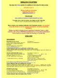
2 It may be a consequenceof an inappropriate mounting or unequal width of thebusbars or insulator slots. In such cases, load sharingwill be uneven and the weakest section may fail. Thiscan be illustrated as follows:1As shown in Figure (a) as a result of loose fit ofbusbars with an unequal gap, the insulators (shadedin the figure) may fail for the following reasons: Misalignment of insulators may cause an unequaldistribution of forces. A loose fit of busbars inside the slots may causeexcessive vibrations on a fault and may lead toloosening of the fasteners and shearing of the wedgesand/or the edges and the fingers of the the insulator mounting section X X maybecome vulnerable to one or all of the busbars are shorter in width asshown in Figure (b)
3 The upper insulator may failat the shaded parts through the wedges or the edges,as they will now encounter relatively higher busbars within the slots give rise to vibrationsand a humming noise due to magnetic may lead to loosening of fasteners and bedetrimental to the performance of the busbar systemin the long run. To lessen the effect of this, the busbarsshould be only marginally loose inside the slot foreasy movement during expansion or contraction. Thisrequires accurate size of insulators and their correctmounting and alignment as shown in Figure (c).
4 In this case all the load-bearing members are equallyinvolved in sharing the force and make the systemstable and may consider a factor of safety of 50 100%,depending upon the criticality of the installation inall the forces that may arise on an actual fault toensure a foolproof Making a jointThis requires special precautions for both aluminiumand copper, as both metals are highly susceptible tooxidation and corrosion (at ordinary temperaturesaluminium being more susceptible than copper). Oxidesof aluminium and copper are poor conductors of heatand electricity and must be avoided, particularly at jointsrather than in the straight lengths, to ensure propertransmission of current from one section of the bus toanother.
5 Also, aluminium is soft. Making a perfect jointto achieve a longer durability is therefore essential. Itinvolves attaining the least contact resistance by ensuringproper contact pressure to eliminate any localized slightly faulty joint may yield to faster erosion of themetal and relaxation of the contact pressure. Loose contactpressure will lead to high contact resistance and cause ahigh localized heat, which may result in ultimate failureof the joint. For instance, if the outer diameter, thicknessor the hole of the washer is not commensurate with thediameter of the hole in the busbar then the washer maygradually sag into the hole, in normal service, throughpressure by the bolt and heat of the buses.
6 Gradually itmay loosen its grip at the joint, release the contact pressureand lead to failure of the contact resistance can be minimized by increasingthe pull of the fasteners. Increasing the area of overlapmay not reduce the contact resistance, unless the numberof fasteners is also increased. It is mandatory to maintaina certain minimum contact pressure per unit area of thejoint overlap. An average contact pressure at around 40 55 kg/cm2 for aluminium and roughly 150 200% of thisfor copper joints is considered adequate to provide areasonable low contact resistance.
7 Too much pressure isalso not advisable as it may result into a cold flowing ofmetal and loosen the contact pressure with passage oftime. For the purpose of easy application, it is expressedin terms of bolt torque, depending upon the area of overlapand the number of fasteners, as specified in Table following are more precautions that are consideredmandatory for making a good joint:1 Before making the joint, clean the surface and applythe contact grease to avoid oxidation, as discussed inSection (iv).2 Make the joint immediately after the above of insulators and busbarsxx FmFmaxx XXFmb1b2 FmFm(a)(b)(c)(a) Smaller thickness of busbars a It may cause vibrations within the insulator slots during a fault andmagnify forces acting on the insulators and fasteners(b) Unequal width of busbars b (b1, b2)The insulator may shear off at Section X X or yoke y(c) Proper mountingFmY29/1042 Electrical Power Engineering Reference & Applications Handbook3 Make the joint by using the correct size of bolts, nutsand washers.
8 Refer to Table for the recommendednumber and size of fasteners for different widths ofbus sections and Table for the recommendedsize of washers for different sizes of bolts. Seealso Figures (a) and (b) for a correct jointing large bus sections it may be advisable touse pressure plates to avoid excessive local pressureas illustrated in Figure a torque wrench (preferably motorised) to tightenthe fasteners to ensure correct surface-to-surfacecontact of the current-carrying parts (Figure (c)).The recommended values of bolt torque are given inTable A pressure that is too high may causerelaxation of the joint by cold flow and must also Section on sealing of bus Straight-through jointsTo join two sections of a bus, fishplates are used asillustrated in Figure Slotted holes are usuallyprovided in the fishplate to allow for fixing are not meant to absorb the thermal expansion ofthe busbars on load, for they are supposed to make arigid joint.
9 Hence there is no scope for surface typical sizes of slots, refer to Table , and forwashers, Table Smaller sections and single busbarscan also be joined by simple overlapping as shown inFigure Same procedure and technical requirementswould apply for aluminium and copper busbars. See alsoFigure (c)Use of manual torque wrench to tighten thefasteners (motorised spanners are employed for faster production)Bolt headPlain + washerBoltNutMin. 2 threadsto + 32 DFigure (a)Correct procedure for using a bolt and nutassembly2D + 3 BusbarSpring washerPlain washerBoltAt least2 threadsBusbarBusbarmountingsupportSpring washerPlain washerConical insulatorBoltMountingstructureFigure (b)
10 A typical mounting and fixing arrangement ofa conical insulator and a flat busbarElevationSide viewRecommended practices for mounting buses and making bus joints29/1043 Table busbar overlaps for different sizes and torques of fastenersBarLength ofBoltDimensionsBolt sizeHoleMinimumTypical size ofwidthoverlaparrangement(Figure )diameterrecommendedslots for fishplatesas indicatedbolt torqueor straightin Figure joints(Figure )123456 M6 18aThese torque values will normally require high tensile copper busbars the torque may be raised by 150 200% of for tee joints even up to the width of bar will be adequate.