Transcription of CONTENTS Heating & Air Conditioning 1E78
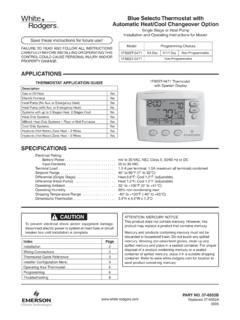
1 CONTENTS . 1. Thermostat 1. Installation Instructions for Removing Old 1. Heating & Air Conditioning Mounting and 2. Check Thermostat 3. 1E78 4. 4. Non-Programmable Heat Only Thermostat YOUR THERMOSTAT REPLACES. Typical System Compatibility Chart 1E78. 1 PREPARATIONS. Standard Heat Only Two Wire Gas or Oil Fired Systems (24 volt) Yes Assemble tools required as shown below. Electronic Ignition Heat Only Two Wire Systems (24 volt) Yes Electronic Ignition Heat Only Gas or Oil Fired Systems (24 volt) Yes Standard Heat/Cool Systems (24 volt) No FLAT BLADE SCREWDRIVER. Heat/Cool Systems Electric Heat (24 volt) No Heat Only Electric Heat Systems (24 volt) No HAND OR POWER.
2 Cool Only Systems No DRILL WITH 3/16 INCH. DRILL BIT, IF NEEDED. Heat Pump Systems (No Aux. or Emergency Heat) No Hot Water Zone Heat Only (Two Wire) Systems Yes WIRE CUTTER/STRIPPER. Hot Water Zone Heat Only (Three Wire) Systems No Line Voltage Heating or Baseboard 110/240 Volt Systems No Millivolt Systems Floor or Wall Furnaces Yes Failure to follow and read all instructions carefully 12 VDC Mobile Home Application Yes before installing or operating this control could cause Multistage Systems No Systems Exceeding 30 VAC, Amp No personal injury and/or property damage. 2 THERMOSTAT DETAILS 3 REMOVING OLD THERMOSTAT.
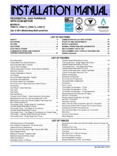
3 Mounting ! CAUTION. Hole To prevent electrical shock and/or equipment damage, disconnect electric power to system at main fuse or circuit breaker box until installation is complete. Before removing wires from old thermostat's switching subbase, label each wire with the terminal designation it was removed from. W904. RC G RH W 1. Remove Old Thermostat: A standard heat/cool thermostat Y O B. consists of three basic parts: W905 a. The cover, which may be either a snap-on or hinge type. b. The base, which is removed by loosening all captive screws. c. The switching subbase, which is removed by unscrewing the mounting screws that hold it on the wall or adaptor plate.
4 Mounting Back of 2. Shut off electricity at the main fuse box until installation is Base Hole Thermostat Body complete. Ensure that electrical power is disconnected. W904 - clip for Celcius display 3. Remove the front cover of the old thermostat. With wires W905 - clip for hydronic system still attached, remove wall plate from the wall. If the old thermostat has a wall mounting plate, remove the thermostat NOTE: Earlier models refer to 37-7006 for jumper locations. and the wall mounting plate as an assembly. Figure 1. Thermostat 4. Identify each wire attached to the old thermostat using the labels enclosed with the new thermostat.
5 5. Disconnect the wires from the old thermostat one at a time. DO NOT LET WIRES FALL BACK INTO THE WALL. 6. Install new thermostat using the following procedures. PART NO. 37-6620C. Replaces 37-6620B. 1041. 3 REMOVING OLD THERMOSTAT ! CAUTION. Take care when securing and routing wires so they do continued from first page not short to adjacent terminals or rear of thermostat. ATTENTION! This product does not contain mercury. How- Personal injury and/or property damage may occur. ever, this product may replace a unit which contains mercury. Do not open mercury cells. If a cell becomes damaged, do not touch any spilled mercury.
6 Wearing non-absorbent gloves, TERMINAL CROSS REFERENCE CHART. take up the spilled mercury and place into a container which New Thermostat Other Manufacturers'. can be sealed. If a cell becomes damaged, the unit should be Terminal Designation Terminal Designation discarded. RH 4 RH M. W W W H. Mercury must not be discarded in household trash. When the unit this product is replacing is to be discarded, place in a suit- able container. Refer to for location to Attach Thermostat Base to Wall send product containing mercury. 1. Remove the packing material from the thermostat. Gently pull the body straight off the base.
7 Forcing or prying on the thermostat will cause damage to the unit. 4 MOUNTING AND WIRING 2. Connect wires beneath terminal screws on base using ap- propriate wiring schematic (see fig. 2). ! WARNING 3. Place base over hole in wall and mark mounting hole loca- tions on wall using base as a template. Do not use on circuits exceeding specified voltage. 4. Move base out of the way. Drill mounting holes. Higher voltage will damage control and could cause 5. Fasten base loosely to wall, as shown in fig. 1, using two shock or fire hazard. mounting screws. Adjust until level, and then tighten screws. Do not short out terminals on gas valve or primary (Leveling is for appearance only and will not affect thermostat control to test.)
8 Short or incorrect wiring will operation.) If you are using existing mounting holes, or if holes damage thermostat and could cause personal injury drilled are too large and do not allow you to tighten base and/or property damage. snugly, use plastic screw anchors to secure subbase. Thermostat installation and all components of the 6. Push excess wire into wall and plug hole with a fire-resistant system shall conform to Class II circuits per the material (such as fiberglass insulation) to prevent drafts from NEC code. affecting thermostat operation. Hydronic (Hot Water or Steam) Battery Location Heating Systems This thermostat requires 2 AAA alkaline batteries to operate.
9 This thermostat is set to operate properly with a forced-air Heating If appears on the display, the batteries are low system. If you have a hydronic Heating system (a system that and should be replaced with fresh premium brand AAA alkaline heats with hot water or steam), you must set the thermostat to batteries such as Duracell or Energizer . The batteries are operate properly with your system. located on the back of the thermostat body (see fig. 1). The factory default setting is forced air heat. Clipping jumper W905 on the circuit board will produce a longer Heating cycle which is normally for hot water or steam (hydronic) systems.
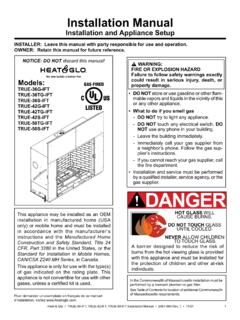
10 Both JUMPER. WIRE. settings produce a very accurate temperature control and can THERMOSTAT. B O Y G W RC RH. be set to your personal preference. As received, the thermostat SYSTEM. cycles the system just under 1 F. With W905 clipped, the system Heating cycles at approximately F. System Hot 24 VAC 120 VAC. Neutral TRANSFORMER. Figure 2. Typical wiring diagram for heat only, 2-wire, single transformer systems 2. 5 CHECK THERMOSTAT OPERATION. NOTE. To prevent static discharge problems, touch side of thermostat to release static build-up before touching any keys. If at any time during testing your system does not operate properly, contact a qualified service person.