Transcription of Contents i Transfer Switches— Medium Voltage - Eaton
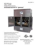
1 Transfer switches Medium Voltage October 2015. Sheet 12001. Medium Voltage Contents Transfer switches Transfer switches Medium Voltage Medium Voltage Vacuum Breaker Transfer switches i ii General Description .. Automatic Transfer Control (ATC).. 1. Protection and Metering .. Auxiliary Equipment .. Available Ratings .. 2. Technical Data.. Layout Dimensions Standard Metal-Clad .. 3. Layout Dimensions Arc-Resistant Metal-Clad.. Specifications 4. See Eaton 's Product Specification Guide, available on CD or on the Web. CSI Format: .. 1995 2010 5. Medium Voltage Vacuum Breaker Transfer switches .. Section 16495 Section 26 36 6. 7. 8. 9. 10. 11. 12. 13. 14. 15. 16. 17. 18. 19. 20. Medium Voltage Transfer Switch Conforming to UL 1008A. 21. CA08104001E For more information, visit: Transfer switches Medium Voltage Vacuum Breaker Transfer Switch (VCP-W-ATC) October 2015. Sheet 12 002. General Description i Reliability and Control with Metal-Clad Standard Control Features Vacuum Technology and The metal-clad switchgear with MV ATS control is provided by Eaton 's drawout vacuum circuit breakers used ATC-900 automatic Transfer controller.
2 Ii Microprocessor-Based Logic for Medium Voltage Transfer switch is Some of the standard features of designed, manufactured and tested in ATC-900 are as follows. Refer to accordance with the latest applicable Eaton 's Technical Data TD140001EN for 1 standards of: complete details of ATC-900. features and capabilities. UL 1008A dated March 2012 . standard for Medium Voltage Lights: 2 Transfer switches Normal position IEEE dated 1999 Emergency position 3 standard for metal-clad switchgear Normal source available ANSI dated 2002 . conformance test procedures Emergency source available 4 NEMA SG-5 power switchgear Undervoltage/overvoltage, assemblies underfrequency/overfrequency CSA No. 31-04 dated sensing on Source 1. 5 January 2004 CSA standard for Undervoltage/overvoltage, switchgear assemblies underfrequency/overfrequency ANSI and IEEE standards for high sensing on Source 2. 6 Voltage AC circuit breakers Timers: IEEE , ANSI Time Delay Normal to Emergency and 2009, and IEEE 7 and 2009.
3 Time Delay Emergency to Normal Time Delay Engine Start Medium Voltage Vacuum Available as an option Type 2B. Time Delay Engine cool-off 8 Breaker Transfer Switch arc-resistant design conforming to IEEE dated 2007, guide for Time Delay Emergency Failure Eaton 's Electrical Sector is an innovator testing metal-enclosed switchgear Time Delay Neutral of low and Medium Voltage manual 9 Transfer switches and has expanded for internal arcing faults Time Delay pre- and/or these capabilities into Medium Voltage The MV ATS style is perfect for any post- Transfer automatic Transfer switches (MV ATS) emergency or backup system and 10 conforming to UL 1008A that combine suitable for service entrance use. It Programmable engine test mode proven vacuum technology and micro- provides reliable automatic Transfer and test run timer processor-based logic. to standby power when: Source 1 available one Form C. 11 contact Why Use Vacuum Circuit Breakers The normal power source fails Source 2 available one Form C.
4 Peak shaving is used 12 Instead of Load Interrupter contact The power source is unreliable Communication via Modbus RTU, switches for Automatic Transfer ? Backup power is mandated by code USB (for flash drives), Modbus Vacuum circuit breakers are suitable 13 for multiple switching (5000 10,000. or local regulations TCP/IP (optional). Eaton manufactures all MV ATS basic Real-time clock and date or even more) operations between sources involved in automatic components and provides one year full Phase reversal on Source 2. 14 Transfer system. Duty cycle of load warranty, eliminating problems that Phase reversal on Source 1. interrupter switch is limited (5 to 50 can arise with multiple warranties for a Go to Emergency feature operations) by IEEE single piece of equipment. Assembly 15 and manufacturing is completed in Preferred source selector for use on Vacuum circuit breakers are rated for systems comprised of utility/utility both load current switching as well ISO certified facilities.
5 Or utility/generator 16 as interrupting fault currents, where Seismic Qualified Overcurrent lockout feature as the load interrupter switches are Plant Exerciser with fail-safe feature rated for load current switching only Eaton 's Medium Voltage circuit 17 breaker Transfer switch assemblies Automatic or manual Vacuum circuit breakers allow use of various relay schemes (for example, are seismically tested or qualified by pushbutton re- Transfer selection phase and ground overcurrent, analysis based on actual testing done PT ratio set points 18 under and overvoltage, under and on similar equipment, to exceed the Closed Transition with Default to overfrequency, directional overcur- requirements based upon 2009 IBC In-Phase Transition with Default to rent, directional power, differential, parameters and CBC 2010. Time Delay Neutral (for closed 19 etc.) for protection and coordination transition switches only). as desired for a given application. Relaying schemes are either not 20 possible or very limited when using load interrupter switches Drawout circuit breakers are easily 21 maintainable For more information, visit: CA08104001E.
6 Transfer switches Medium Voltage October 2015 Vacuum Breaker Transfer Switch (VCP-W-ATC). Sheet 12 003. General Description Additional Options Operation Maintenance Lockout on phase and/or ground Operation is by a motor-charged The stored energy mechanism and i overcurrents and/or internal stored energy spring mechanism control components are easily accessi- bus faults charged by a universal electric motor, ble and can be inspected by removing or a manual levering tool in an emer- the front panel. Minor maintenance ii Load current, power and PF. gency. The stored energy mechanism when required, such as lubricating the metering with optional DCT module is a true mechanically and electrically mechanism and accessing the control 24 Vdc control power input trip-free design, meaning that while components, is simplified. 1. Up to four additional I/O modules, holding a mechanical trip command, each with four programmable the breaker contacts will not close or Operation Sequence digital inputs and digital outputs touch while receiving an electrical or Transfer is initiated by Eaton 's ATC-900 2.
7 Overcurrent protection: mechanical close command. microprocessor-based logic controller mounted on the door. Normal Each CBS is electrically operated by 3. Emergency these control voltages: 120 Vac close The ATC-900 can be programmed and ac capacitor trip, or 48 Vdc, for open or closed transition. The Eaton 's Power Xpert . and IQ metering: normal and 125 Vdc or 250 Vdc. AC control Voltage controller will not initiate the closed 4. is derived from potential transformers Transfer until both power sources are emergency connected in the line side of each CBS. synchronized in Voltage , frequency Space heater and phase angle. If a power source is 5. The DC control Voltage is provided by Partial discharge InsulGard relay the user. lost, the closed transition control will return to the open mode. Circuit Breaker switches Controls and indicators are functionally ATC controller capabilities include: 6. grouped on the front control panel and Switching is provided by Eaton 's include: closing spring status, close VCP-W Vacuum Circuit Breakers in Continuous monitoring of all three ANSI voltages of 5 and 15 kV.
8 And trip button, operation counter, phases of all loads and Voltage on 7. contact status indicators and a T . the source and bus Circuit breaker switches (CBS) are handle latch (located at the bottom of Generator testing under load horizontal drawout types up to 15 kV. the control panel). Each CBS includes 8. a control switch, and red and green Simplified, custom programming The CBS includes five major lights to indicate the CBS contact on the faceplate keypad to meet components: vacuum interrupter pole units, stored energy mechanism, position. specific user requirements. There 9. are no DIP switches to set push rod assembly, primary discon- Contacts Visual status indications of both necting contacts, and removable glass Primary disconnects are silver-plated sources and the load. 10. polyester insulating barriers. copper. Secondary contacts are silver- Easy-to-use: plated and automatically engage in Vacuum Interrupters At-a-glance overview of the MV. Each CBS includes three vacuum the CBS operating position.
9 They can ATS status and parameters and 11. be manually engaged in the CBS. interrupters, separately mounted in test position. key diagnostic data a self-contained, self-aligning pole Real-time values for volts and 12. unit that is easily removed. A direct Safety frequency can be viewed on the reading contact erosion indicator Double deadfront shields isolate the LED display plus the power is clearly visible when the CBS is operator from high Voltage when the source in use 13. withdrawn from the compartment. CBS is energized. The CBS can be Displays historical information Each vacuum interrupter pole unit is connected or disconnected with the including Source 1 and Source 2. mounted on glass polyester supports compartment door closed by a run time, available time, and 14. for 5 kV and 15 kV ratings. manually operated levering device. connected time, load energized The unique, nonsliding current Safety interlocks provide for the time, number of transfers, and the Transfer system from the movable mechanism to be held mechanically date, time and reason for the last 15.
10 Vacuum interrupter stem to the CBS trip-free during racking. Closing 100 transfers consists of a series of tin-plated, high springs will discharge automatically conductivity copper leaf conductors. when the CBS is being withdrawn. Oscillographic data for last 16. 10 transfers can be downloaded The conductors are swaged onto the via USB port or displayed in the movable vacuum interrupter stem and provide: controller's display window 17. Improved current flow because the multi-point contact offers very low 18. electrical resistance No required maintenance because the current Transfer from the 19. movable stem to the CBS primary conductor is a nonsliding and nonrolling design 20. Longer vacuum interrupter life 21. CA08104001E For more information, visit: Transfer switches Medium Voltage Vacuum Breaker Transfer Switch (VCP-W-ATC) October 2015. Sheet 12 004. General Description i ATC-900 Open Transition Transfer ATC Controller While the load is connected to Source 2, the ATC-900 controller continues to When the system is operating from the monitor Source 1.


