Transcription of CONTINENTAL MOTORS AIRCRAFT ENGINE …
1 Box 90 Mobile, AL 251-436-8299 PAGE NO DOC NO REVISION2017/10/201 of 6SB17-06 2017 CONTINENTAL MOTORS , 3SB17-06 TECHNICAL PORTIONSFAA APPROVEDCONTINENTAL MOTORS AIRCRAFT ENGINESERVICE BULLETINC ontains Useful Information Pertaining To Your AIRCRAFT EngineSUBJECT: Connecting Rod Bolt, (P/N 655959) and Crankcase Clearance InspectionPURPOSE:To inspect connecting rod bolt/crankcase clearance after connecting rod bolt : Anytime connecting rod assembly or connecting rod bolts are replaced, perform the inspections set forth in this Service Document prior to further ENGINE :All CONTINENTAL MOTORS (CMI), IO-360 (except AF), and L/TSIO-360 aviation gasoline (AvGas) engines originally manufactured or rebuilt prior to GENERAL INFORMATIONC ontinental MOTORS , Inc.
2 (CMI) has received field reports of connecting rod bolt heads (P/N 655959) experiencing interference with the crankcase rib during ENGINE drive train assembly on crankcases produced prior to 2011. II. SCOPEI nspect affected engines for crankcase rib clearance when installing connecting rod bolt (P/N 655959) after connecting rod assembly or connecting rod bolts are replaced. All 360 engines manufactured or rebuilt after 2010 are not affected by this Service Bulletin. This Service Document contains updates to the manufacturer's Instructions for Continued Airworthiness as additional inspection criteria for determining serviceable condition during overhaul.
3 This procedure should be added to the ENGINE Drive Train Inspection Checklist and a copy of this bulletin must be inserted into the most current version of the applicable Maintenance and Overhaul manuals (as listed in the Models Affected ) until the data is incorporated into the manual, by revision, or the service bulletin is retired. III. ACTION REQUIREDP erform the following crankcase/connecting rod bolt clearance inspection for each crankcase half when replacing connecting rod bolts on affected CMI ENGINE models.
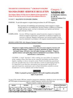
4 Connecting rod assemblies are selected in pairs with a maximum weight variation not to exceed 1/2-ounce in opposing cylinders. Replace connecting rods assemblies only in pairs. 1. Before crankshaft assembly, place the 1-3-5 crankcase on it s side and install all bearings and thrust washers to support the crankshaft assembly. Lay crankshaft assembly on the main bearings in the crankcase half (see Figure 1). Box 90 Mobile, AL 251-436-8299 PAGE NO DOC NO REVISION2017/10/202 of 6SB17-06 Figure 1. Crankshaft, Main Bearings, and Thrust Washers, 1-3-5 side typical2.
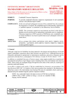
5 Insert the connecting rod bolt (with chamfer facing outward) into the connecting rod cap. Seat and hold the connecting rod (cap, bearing and bolt) assembly, over the first rod journal with connecting rod bolt head facing toward crankcase rib (see Figure 2). Figure 2. Rotate Crankshaft, Connecting Rod Cap, Bearing and Bolt3. Carefully rotate the crankshaft assembly in the 1-3-5 crankcase while simultaneously rotating (circumvolving) the connecting rod (cap, bearing, and bolt) assembly around the first journal to ensure the connecting bolt head achieves complete clearance past the crankcase rib.
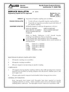
6 Box 90 Mobile, AL 251-436-8299 PAGE NO DOC NO REVISION2017/10/203 of 6SB17-06 4. If contact is made between the connecting rod bolt head and crankcase rib, mark the crankcase rib with a permanent marker on both sides of the bolt head (as shown in Figure 3). Figure 3. Mark Crankcase/ Bolt Head Interference Points / Area, typicalFigure 4. Connecting Rod Bolt Head Clearance Areas, 1-3-5 side crankcase Box 90 Mobile, AL 251-436-8299 PAGE NO DOC NO REVISION2017/10/204 of 6SB17-06 WARNINGN ever remove material from connecting rod assemblies (including bolt head).
7 Connecting rods are matched to limit ENGINE vibration with no more than 1/2 ounce weight variance between connecting rod assemblies in opposing cylinders. Removing material from a connecting rod will destroy the shot peen treatment and may cause stress : Wear eye protection when using grinders to avoid injury from flying debris. 5. Using a die grinder or pencil grinder, remove ONLY enough crankcase rib material from the marked crankcase to achieve connecting rod bolt head clearance of (see Figure 5).
8 Figure 5. Crankcase Clearance Modification, typical6. Repeat Step and Step 5. until clearance is achieved under all conditions. Using a flat feeler gauge, verify crankcase rib clearance of is provided for all connecting rod bolt heads (see Figure 6). Box 90 Mobile, AL 251-436-8299 PAGE NO DOC NO REVISION2017/10/205 of 6SB17-06 Figure 6. Verify Clearance At All Interference Points, Feeler Gauge Measurement7. Inspect the crankcase clearance surfaces and remove all nicks, burrs, sharp angles or edges using a de-burring tool and Scotch-Brite wheel (ultra fine or equivalent).
9 Evenly shape, taper, and smooth all interfering crankcase rib surfaces where material was removed (see Figure 7). 8. Clean crankcase to remove all burrs and metal shavings. Figure 7. Crankcase Finished Surface, Box 90 Mobile, AL 251-436-8299 PAGE NO DOC NO REVISION2017/10/206 of 6SB17-06 9. Use an alodine touch up pen (Alodine 1132 Touch-N-Prep Coating, Henkel Corporation) or equivalent (as specified by MIL-DTL-81706B, (PIN M817061A6D)) to apply alodine to machined areas or any other areas of exposed metal, as instructed by the ENGINE s primary Instructions for Continued Airworthiness (ICA).
10 10. Repeat all steps (Step 1. through Step 9.) to achieve connecting rod bolt head clearances for the 2-4-6 crankcase After achieving the crankcase inspection and clearances for all ENGINE connecting rod bolt heads and completing the protective alodine treatment to both machined crankcase halves,install the crankshaft assembly in the crankcase according to Instructions for Continued Airworthiness (ICA) and verify connecting rod bolt head Create a logbook entry indicating compliance with this Service Document (SB17-06).