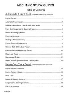
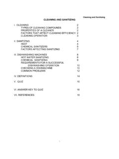
Transcription of CONTINENTAL MOTORS AIRCRAFT ENGINE SERVICE …
1 CONTINENTAL MOTORS AIRCRAFT ENGINE CATEGORY 4. SERVICE INFORMATION DIRECTIVE SID05-1B. Supersedes SID05-1A. Compliance Will Enhance Safety, Maintenance or Economy of Operation TE CHN ICA L P O RTI O NS. FAA APPROVED. SUBJECT: Inspection Guidelines for CM Camshafts . and Hydraulic Lifters PURPOSE: To provide SERVICE information on the basic material, inspection criteria and maintenance of the camshaft and hydraulic lifters. To explain the warranty policy guidelines if warranty issues are assessed on CM camshafts and lifters. COMPLIANCE: CM recommends inspection described only if the indications defined are found. In the absence of such indications, no action is needed or recommended. MODELS. AFFECTED: All new and rebuilt CM AVGAS engines. I. Scope This SERVICE Document contains the instructions for Continued Airworthiness to inspect hydraulic lifters and their associated camshaft lobes on in- SERVICE AVGAS engines.
2 It also explains the criteria and indications to determine if a detailed inspection is required. NOTE: CM lifters are a 100% replacement item at overhaul. II. Background In CM engines, the camshaft is located below the crankshaft and is driven by a gear set from the crankshaft at one-half the speed of the crankshaft. The camshaft lobes on a camshaft control individual valve lift and duration. The links between the camshaft and the valves are the hydraulic lifter, the push rod and the rocker arm. Figure 1. Illustration ISSUED REVISED PAGE NO DOC NO REVISION. 2005/01/04 2016/06/16. Box 90 Mobile, AL 251-436-8299. 1 of 10 SID05-1 B. 2016 CONTINENTAL MOTORS , Inc. A. Operation, Hydraulic Lifter The hydraulic lifter performs two functions. The hydraulic lifter's main function is to take up clearance in the valve train. The clearance between the lifter body and the plunger is a precision fit that allows a specified amount of oil to bleed off around the plunger when it is compressed.
3 Secondly, it provides an interface between the camshaft lobe and the remaining valve train. This allows conversion of the cam lobe profile into a linear movement for actuation of the intake and exhaust valves. Figure 2. Hydraulic Lifter Cross Section 1 Retaining Ring 5 Oil Reservoir 9 Plunger 2 Push Rod End Socket 6 Check Ball Valve 10 Steel Body 3 Interior Body Groove 7 Expanding Spring 11 Oil Inlet Hole 4 Outside Groove 8 Check Valve Housing/Assembly ISSUED REVISED PAGE NO DOC NO REVISION. 2005/01/04 2016/06/16. Box 90 Mobile, AL 251-436-8299. 2 of 10 SID05-1 B. B. Materials The material of the camshaft is AIRCRAFT quality steel with the cam lobes treated by carburizing for additional hardness and wear resistance. The lifter body is made of cast iron with the face being chilled during casting to provide an extremely hard wear-resistant material. During manufacture, the lifter face and cam lobes are also coated with a manganese phosphate coating to resist rust and lower friction during the initial hours of ENGINE operation (see Figure 3).
4 Figure 3. Camshaft and Lifter Interface, typical C. Wear Factors The interface between a cam lobe and lifter will experience normal wear as the ENGINE operates. Normal wear may take the form of a bright shiny uniform wear surface, with a circular pattern visible on the lifter face. Minimal wear material will be collected by the oil and trapped in the oil filter element or screen. Localized areas may show minor signs of galling or spalling under normal SERVICE due to various operating conditions. Figure 4. Typical Lifter Faces from SERVICE ISSUED REVISED PAGE NO DOC NO REVISION. 2005/01/04 2016/06/16. Box 90 Mobile, AL 251-436-8299. 3 of 10 SID05-1 B. 1. Galling Galling results from a breakdown in lubrication allowing bare metal to metal contact. Bonding of one of the materials to the other can result, transferring a small amount of material. 2. Spalling Spall wear initially appears in small areas on the lifter face that have begun to separate, leaving shallow pits.
5 Because the camshaft is constructed from steel and the lifter body from iron; rust and corrosion are the most common cause of spalling. 3. Foreign Materials Foreign material between the cam lobe and lifter can result in very high local loads on the surfaces and break down a local area of the lifter. Foreign material may also stop a lifter from rotating in the bore. This results in one area being loaded constantly and can also lead to spalling. D. Wear Effects on Cam Lifter The cam lobe/lifter interface is designed to undergo normal wear during SERVICE life allowing the lifter and cam lobes to break in together; similar to piston rings in a cylinder bore. Such wear is normal as are circular wear patterns on the face of the lifter and polishing of the cam lobes. Circular scratches may also result from hard particle passage and will not effect operation. Normal minor spalling caused from corrosion or other factors will not affect operation as the loads are redistributed to the surrounding material.
6 Minor spalling will appear as separated spalled areas with polished contact patterns on the remainder of the face (see Figure 5). NOTE: The hydraulic feature of the lifter continuously adjusts for normal wear. Figure 5. Indications of Minor Spalling Major spalling that involves much of the face will usually have no effect on operation and will frequently heal over ; reestablishing a stable surface for the cam interface. The short-term effect on the cam is generally insignificant. The discarded material from spalling will be minimal and deposit in the filter element or screen. ISSUED REVISED PAGE NO DOC NO REVISION. 2005/01/04 2016/06/16. Box 90 Mobile, AL 251-436-8299. 4 of 10 SID05-1 B. In infrequent cases, lifter deterioration will cause significant wear to the cam lobe and the lift of the valve may be reduced. Extreme corrosion leads to reduced power performance in the affected cylinder. The hydraulic lifter also has a limited range of adjustment and can run out of travel indicated by an audible tapping noise from the ENGINE .
7 In some cases, significant spalling may result in some damage to the cam lobe apex. This level of damage is very rare, but will manifest itself as surface cracks on the nose with moderate depth. corrosion /rust will also cause cam lobe distress. See steps 5 through 8, Perform visual inspection of cam lobe using an inspection light. on page 8. for detailed information. NOTE: The appearance of the cam lobe apex may vary normally, and only if such cracks are present should the camshaft be considered a candidate for replacement. III. Distress Detection As with other wearing parts in the ENGINE , the normal means of detecting excessive wear are through examination of the oil filter element or screen at each oil change. Extreme wear may also be detected by audible noise from the valve train indicating a lifter that is not pumping up properly. In the absence of such indications, no action is needed until the next ENGINE overhaul.
8 If material is observed in the filter and believed to be from the lifters, perform an inspection according to the instructions in (see Section IV, Inspection Criteria and Maintenance, on page 6). Figure 6. Full Face Spalling Figure 7. corrosion Etching On Lifter Body ISSUED REVISED PAGE NO DOC NO REVISION. 2005/01/04 2016/06/16. Box 90 Mobile, AL 251-436-8299. 5 of 10 SID05-1 B. A. Tips to Avoid Distress 1. Monitor ENGINE Usage, Flight Frequency, Oil Quality, and Oil Changes CAUTION: Infrequently flown AIRCRAFT must have frequent oil changes to reduce wear distress. Compliance with the latest revision of M-0, Standard Practice Maintenance Manual and your applicable ENGINE Maintenance and Overhaul Manual is required. Distress issues can be reduced by sustaining frequent flight operations under normal oil temperatures. A minimum 30 minute cruise flight is required (oil temperatures are stable at 170qF to 200qF range).
9 This function assists the removal of moisture and acids from the system. As a result of such frequent operation, fleet operators rarely experience excessive corrosion or distress. CM requires that AIRCRAFT that are not flown on a regular basis have the oil and filter changed at least four times a year. Adhere to the latest revision of M-0, Standard Practice Maintenance Manual for corrosion prevention. 2. Cold Weather Operations Pre-heating using crankcase heaters is an effective means of warming an ENGINE . However, the warming and cooling process can also condense moisture into the oil aggravating corrosion issues. See the latest revision of M-0, Standard Practice Maintenance Manual for more information on this subject. 3. Use Only Approved Oil Use only approved lubricants as specified in the latest revision of M-0, Standard Practice Maintenance Manual. IV. Inspection Criteria and Maintenance If materials are detected from an examination of the oil filter element or screen, oil suction screen or drain plug, or if an audible noise from the valve train is detected, the lifters and cam lobes must be examined as described below.
10 No in- SERVICE examination is needed in the absence of such indicators or audible noise from the valves. 1. Using the airframe manufacturer's maintenance instructions remove ENGINE cowlings and cooling baffles as necessary to gain access to the cylinders for valve cover removal . 2. Using the appropriate ENGINE overhaul or maintenance manual, remove the lifters as follows: WARNING. Verify master switch is in the OFF position. Verify magneto switches are connected to the magnetos and in the OFF . position. Verify P leads are grounded while working in close proximity to the propeller. CAUTION: Mark all removed parts for reinstalling in the same position from which they were removed. a. Remove valve covers from the cylinders. b. Position the crankshaft so that the matching valve for each cylinder is fully closed. ISSUED REVISED PAGE NO DOC NO REVISION. 2005/01/04 2016/06/16. Box 90 Mobile, AL 251-436-8299.