Transcription of CONTINENTAL MOTORS AIRCRAFT ENGINE SERVICE …
1 CONTINENTAL MOTORS AIRCRAFT ENGINE CATEGORY 4. SERVICE INFORMATION DIRECTIVE SID05-1B. Supersedes SID05-1A. Compliance Will Enhance Safety, Maintenance or Economy of Operation TE CHN ICA L P O RTI O NS. FAA APPROVED. SUBJECT: inspection Guidelines for CM Camshafts . and Hydraulic Lifters PURPOSE: To provide SERVICE information on the basic material, inspection criteria and maintenance of the camshaft and hydraulic lifters. To explain the warranty policy guidelines if warranty issues are assessed on CM camshafts and lifters.
2 COMPLIANCE: CM recommends inspection described only if the indications defined are found. In the absence of such indications, no action is needed or recommended. MODELS. AFFECTED: All new and rebuilt CM AVGAS engines. I. Scope This SERVICE Document contains the instructions for Continued Airworthiness to inspect hydraulic lifters and their associated camshaft lobes on in- SERVICE AVGAS engines. It also explains the criteria and indications to determine if a detailed inspection is required. NOTE: CM lifters are a 100% replacement item at overhaul.
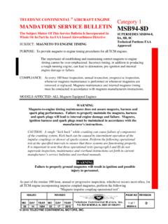
3 II. Background In CM engines, the camshaft is located below the crankshaft and is driven by a gear set from the crankshaft at one-half the speed of the crankshaft. The camshaft lobes on a camshaft control individual valve lift and duration. The links between the camshaft and the valves are the hydraulic lifter, the push rod and the rocker arm. Figure 1. Illustration ISSUED REVISED PAGE NO DOC NO REVISION. 2005/01/04 2016/06/16. Box 90 Mobile, AL 251-436-8299. 1 of 10 SID05-1 B. 2016 CONTINENTAL MOTORS , Inc. A. Operation, Hydraulic Lifter The hydraulic lifter performs two functions.
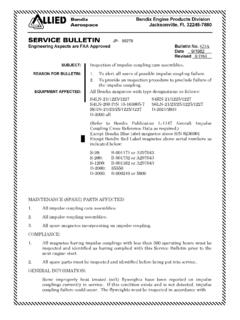
4 The hydraulic lifter's main function is to take up clearance in the valve train. The clearance between the lifter body and the plunger is a precision fit that allows a specified amount of oil to bleed off around the plunger when it is compressed. Secondly, it provides an interface between the camshaft lobe and the remaining valve train. This allows conversion of the cam lobe profile into a linear movement for actuation of the intake and exhaust valves. Figure 2. Hydraulic Lifter Cross Section 1 Retaining Ring 5 Oil Reservoir 9 Plunger 2 Push Rod End Socket 6 Check Ball Valve 10 Steel Body 3 Interior Body Groove 7 Expanding Spring 11 Oil Inlet Hole 4 Outside Groove 8 Check Valve Housing/Assembly ISSUED REVISED PAGE NO DOC NO REVISION.
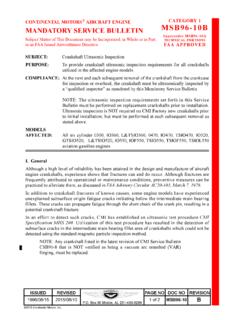
5 2005/01/04 2016/06/16. Box 90 Mobile, AL 251-436-8299. 2 of 10 SID05-1 B. B. Materials The material of the camshaft is AIRCRAFT quality steel with the cam lobes treated by carburizing for additional hardness and wear resistance. The lifter body is made of cast iron with the face being chilled during casting to provide an extremely hard wear-resistant material. During manufacture, the lifter face and cam lobes are also coated with a manganese phosphate coating to resist rust and lower friction during the initial hours of ENGINE operation (see Figure 3).
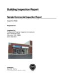
6 Figure 3. Camshaft and Lifter Interface, typical C. Wear Factors The interface between a cam lobe and lifter will experience normal wear as the ENGINE operates. Normal wear may take the form of a bright shiny uniform wear surface, with a circular pattern visible on the lifter face. Minimal wear material will be collected by the oil and trapped in the oil filter element or screen. Localized areas may show minor signs of galling or spalling under normal SERVICE due to various operating conditions. Figure 4. Typical Lifter Faces from SERVICE ISSUED REVISED PAGE NO DOC NO REVISION.
7 2005/01/04 2016/06/16. Box 90 Mobile, AL 251-436-8299. 3 of 10 SID05-1 B. 1. Galling Galling results from a breakdown in lubrication allowing bare metal to metal contact. Bonding of one of the materials to the other can result, transferring a small amount of material. 2. Spalling Spall wear initially appears in small areas on the lifter face that have begun to separate, leaving shallow pits. Because the camshaft is constructed from steel and the lifter body from iron; rust and corrosion are the most common cause of spalling.
8 3. Foreign Materials Foreign material between the cam lobe and lifter can result in very high local loads on the surfaces and break down a local area of the lifter. Foreign material may also stop a lifter from rotating in the bore. This results in one area being loaded constantly and can also lead to spalling. D. Wear Effects on Cam Lifter The cam lobe/lifter interface is designed to undergo normal wear during SERVICE life allowing the lifter and cam lobes to break in together; similar to piston rings in a cylinder bore.
9 Such wear is normal as are circular wear patterns on the face of the lifter and polishing of the cam lobes. Circular scratches may also result from hard particle passage and will not effect operation. Normal minor spalling caused from corrosion or other factors will not affect operation as the loads are redistributed to the surrounding material. Minor spalling will appear as separated spalled areas with polished contact patterns on the remainder of the face (see Figure 5). NOTE: The hydraulic feature of the lifter continuously adjusts for normal wear.
10 Figure 5. Indications of Minor Spalling Major spalling that involves much of the face will usually have no effect on operation and will frequently heal over ; reestablishing a stable surface for the cam interface. The short-term effect on the cam is generally insignificant. The discarded material from spalling will be minimal and deposit in the filter element or screen. ISSUED REVISED PAGE NO DOC NO REVISION. 2005/01/04 2016/06/16. Box 90 Mobile, AL 251-436-8299. 4 of 10 SID05-1 B. In infrequent cases, lifter deterioration will cause significant wear to the cam lobe and the lift of the valve may be reduced.