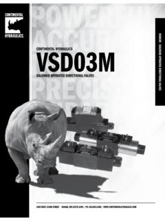
Transcription of CONTINENTVSD03M*-SAL HYDRAULICS
1 VSD03M*-S - SOLENOID OPERATED DIRECTIONAL ANTI-SHOCK VALVES. VSD03M*-S. CONTINENTAL HYDRAULICS . SOLENOID OPERATED DIRECTIONAL ANTI-SHOCK VALVES. 5505 WEST 123RD STREET SAVAGE, MN 55378-1299 / PH: / DURABLE. VSD03M*-S. VSD03M*-S - SOLENOID OPERATED DIRECTIONAL ANTI-SHOCK VALVES. SOLENOID OPERATED DIRECTIONAL ANTI-SHOCK VALVES. DESCRIPTION TYPICAL PERFORMANCE SPECIFICATIONS. These valves conform to NFPA D03 and ISO 4401 mounting standards. As the valve spool shifts, the spool lands cross-over the P - A - B Ports 5000 psi 350 bar valve body ports. This can produce high instantaneous flow rates. MAXIMUM. OPERATING. PRESSURE. The anti-shock valve provides a slow spool movement; slower than T Port 3000 psi 210 bar that of a standard directional valve. This results in reduction or elimination of hydraulic system shock produced by the spool movement and high flow rates.
2 FLOW RATE 20 gpm 76 l/min NFPA D03. MOUNTING SURFACE. ISO 4401-03-02-0-03. MAXIMUM. DC lbs kg WEIGHT. Ambient - 4 to +130 F -20 to +54 C. RANGE TEMPERATURES. Fluid - 4 to +180 F -20 to +82 C. Range 60 -1900 SUS 10 - 400 cSt FLUID VISCOSITY. Recommended 120 SUS 25 cSt FLUID CONTAMINATION ISO 4406:1999 Class 20/18/15. 2 - IDENTIFICATION CODE. VSD03M*-S - SOLENOID OPERATED DIRECTIONAL ANTI-SHOCK VALVES. VSD03M - - S- - L- DESIGN LETTER. SOLENOIDS - See the codes on page 9. FUNCTION SEAL MECHANICAL CONNECTION BOX OPTIONS. OMIT IF NOT REQUIRED OMIT IF NOT REQUIRED. A Buna (STD). Single Solenoid Operator At See the codes on page 8. R. B' Port End. G Viton 1 WD Wash-Down Single Solenoid 2 Position ELECTRICAL OPTION. Spool Type Spring Offset See Next Page Plug-in terminal OMIT. solenoids or lead wires Connection box with B.
3 Terminal posts and lights 3. Dual Solenoid 3 Position Spring Centered 5. Single Solenoid 2 Position Spring Centered 9. Single Operator 2 Position - 3 Way Spring Offset TYPICAL ORDERING CODE: VSD03M-3A-AS-B5A-70L-C. VSD03M-3AC-16-AS-44L-C. - 3. SPOOLS. NAME SYMBOL FUNCTION CENTER POSITION CROSSOVER FUNCTION MATCHING. VSD03M*-S - SOLENOID OPERATED DIRECTIONAL ANTI-SHOCK VALVES. A All ports blocked All ports blocked 1. P B and A T restricted or A1 All ports blocked 3. P A and B T restricted AC-08 All ports blocked All ports blocked 3. AC-16 All ports blocked All ports blocked 3. AC-26 All ports blocked All ports blocked 3. B1 All ports open All ports open 1, 3. P blocked, P blocked, F1 3, 5. A and B restricted to T A or B restricted to T. P blocked, FC-08 All ports blocked 3. A and B restricted to T.
4 P blocked, FC-16 All ports blocked 3. A and B restricted to T. P blocked, FC-26 All ports blocked 3. A and B restricted to T. P T. L1 All ports open, restricted 3, 5. A and B blocked X - All ports blocked 9. These are the standard configurations. Contact Continental HYDRAULICS for special versions. 4 - PRESSURE DROPS P-Q. (OBTAINED WITH VISCOSITY OF 170 SUS - 36 CST AT 70 F - 50 C). VSD03M*-S - SOLENOID OPERATED DIRECTIONAL ANTI-SHOCK VALVES. p p [bar] FLOW CURVE NUMBER. [psid]. 350 25 SPOOL SHIFTED CENTER. 4. 280 20 P A P B A T B T P T. 3. 210 2 15. A, A1 2 2 3 3. 1. 140 10. B 1 1 3 3 2. 70 5. L 4 4 4 4 3. 0 5 10 15 20 [gpm]. Q 9X 3 3. 20 40 60 76 [l/min]. PERFORMANCE CURVE. DC VOLTAGE. CURVE SPOOL. 1 A1. 2 L1. 3 B1, 9X. 4 F1. 5 3AC-26, 3FC-26. 6 3AC-16, 3FC-16. 7 3AC-08, 3FC-08. 8 1A, 1B1.
5 - 5. OVERALL AND MOUNTING DIMENSIONS - CONNECTION BOX VERSION. VSD03M*-S - SOLENOID OPERATED DIRECTIONAL ANTI-SHOCK VALVES. VSD03M, 3* Dimensions in mm [IN]. Connection Box Manual Override Integrated in the Tube. SOL. B' SOL. A'. Mounting surface with sealing rings: Coil Removal 4 pcs. AS568-012. Space 90 Shore A. VSD03M-1*, 5*, 9*. Manual Override Integrated in the Tube. SOL. B'. Coil Removal Space 6 - OVERALL AND MOUNTING DIMENSIONS - DIN STYLE VERSION. VSD03M*-S - SOLENOID OPERATED DIRECTIONAL ANTI-SHOCK VALVES. VSD03M, 3* Dimensions in mm [IN]. Coil with DIN style shape (DIN 43650) Connector Manual Override Integrated in the Tube. SOL. B' SOL. A'. Mounting surface with sealing Coil Removal rings: 4 pcs. Space AS568-012 90 Shore A. VSD03M-1*, 5*, 9*. Manual Override Integrated in the Tube.
6 Coil Removal Space - 7. ELECTRICAL CHARACTERISTICS. Valves are available with an electrical connection box or with DIN 43650 solenoids, Deutsch DT04 or lead VSD03M*-S - SOLENOID OPERATED DIRECTIONAL ANTI-SHOCK VALVES. wires are also available. CONNECTION BOX OPTIONS. To simplify the connections and prevent wiring mistakes, we offer the option of connection boxes with quick connect pin receptacles, already wired. Valves are available with receptacles on solenoid side A' or B' and several connector styles. Below are the codes to be included in the box option' of the ordering code, depending on the version you choose. Wiring diagrams below shows the standard connections for 3-pin, 4-pin and 5-pin connectors. The commercially available mating female connector are not included. CODE PIN SHAPE PORT END NOTES.
7 5A 5 A Single and Dual Male Mini 5H 5 B Solenoid 3A 3 A. Male Mini Single Solenoid Only 3H 3 B. 4A 4 A. D4A 4 A Different Wiring. Male Micro 4 4 B See Schematics. D4 4 B. 5 PIN RECEPTACLE. 1 Lead to Solenoid B. Male mini receptacles conform to 2 Lead to Solenoid A. R1 - 2007 used with 3 Ground Lead (Green). single or double solenoid valve. 4 Lead to Solenoid A. 5 Lead to Solenoid B. 26 mm [1 ] Wrench 3 PIN RECEPTACLE. Male mini receptacles conform 1 Ground Lead (Green). to R1 - 2007 used 2 Lead to Solenoid with single solenoid valve. 3 Lead to Solenoid 26 mm [1 ] Wrench 4 PIN RECEPTACLE 4A & 4 D4A & D4. Male micro receptacles (M12x1 1 Brown Lead to Solenoid A 1 Brown No Connection 2 White No Connection 2 White Lead to Solenoid A. thread) used with DC valve only. 3 Blue Common Lead to Sol.
8 A & B 3 Blue Common Lead to Sol. A & B. 23 mm [7/8] Wrench 4 Black Lead to Solendoid B 4 Black Lead to Solendoid B. 8 - SOLENOIDS. Listed below are the types of solenoids available and the numbers to be added in the solenoid box on page 3. VSD03M*-S - SOLENOID OPERATED DIRECTIONAL ANTI-SHOCK VALVES. PLUG-IN TERMINAL SOLENOID. DIN 43650 DEUTSCH DT04 MALE. This solenoid has three terminal posts. Use bi-polar connectors that meet ISO 4400 / DIN 43650. (EN 175301-803). Protection against atmospheric agent: IP 65. LEAD WIRES. 6 inch length, protection against atmospheric agent: IP 67. DEUTSCH DT04 MALE. Protection against atmospheric agent: IP 69 LEAD WIRES. Connectors must be ordered separately. CONNECTION BOX SOLENOIDS. This is a two-pin solenoid which connects to the circuit board. Wiring is done on the terminal strip inside the box.
9 DEUTSCH. DIN LEAD WIRE BOX VOLTAGE VOLTAGE RESISTANCE INRUSH HOLDING HOLDING. DT04. CONNECTION CONNECTION CONNECTION & FREQ. LIMITS 10% CURRENT CURRENT POWER. CONNECTION. CODE CODE CODE [VOLT - HERTZ] [MIN - MAX] [OHM] [A] [A] [W]. CODE. 42 24K4 24K7 70 24 V DC 21 - 26 30. 44 12K4 12K7 75 12 V DC 10 - 13 30. WASHDOWN OPTION (CODE WD). The wash-down option with the electrical box is designed for an IP65 rating. This option uses a special cover without the mounting bolt access holes and uses silicone sealant to help seal between the coil and core tube. The DIN, Deutsch and lead wire coils versions of the wash-down option uses silicone sealant to help seal between the coil and core tube. - 9. APPLICATION DATA. VSD03M*-S - SOLENOID OPERATED DIRECTIONAL ANTI-SHOCK VALVES. FLUIDS. All pressure drops shown on these data pages are based on 170 SUS fluid viscosity and specific gravity.
10 For any other specific gravity (G1) the pressure drop ( P) will be approx. P1 = P (G1/G). See the chart for other viscosities. FLUID Cst 10 32 36 43 54 65 76 86 108 216 324 400. VISCOSITIES SUS 60 75 150 170 200 250 300 350 400 500 1000 1500 1900. MULTIPIER Use mineral oil-based hydraulic fluids HL or HM type, according to ISO 6743-4. For these fluids, use NBR. seals. For fluids HFDR type (phosphate esters) use FPM seals (code G). For the use of other kinds of fluid such as HFA, HFB, HFC, please consult our technical department. Using fluids at temperatures higher than 180 degrees F causes the accelerated degradation of seals as well as degradation of the fluids physical and chemical properties. From a safety standpoint, temperatures above 130 degrees F are not recommended. Ambient - 4 to +130 F -20 to +54 C.