Transcription of Control and Field Instrumentation Documentation
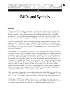
1 897 Control and FieldInstrumentationDocumentationTo successfully work with (and design ) Control systems, it is essential to understand the documents that are typically used to illustrate process con-trol and associated Field Instrumentation . The Documentation of process Control and associated Field Instrumentation is normally created by the engineering firm that designs and constructs the plant. The company that commissioned the plant may have an internal Documentation standard the engineering firm will be required to follow. For an older installation, the plant Documentation may only exist as a series of paper documents. Today the Documentation created for a new or upgraded plant is produced electronically using automated design tools and software. The tools and software selected by the plant or engineering firm for initial plant design or upgrade will influence the Documentation format and how Documentation is maintained at the plant site.
2 Also, the selection of the Control system determines to what extent the system is the automatic creation of documents that follow defined conventions for naming and the Documentation generated by the Control system does not follow standards that have been established for process Control and instrumenta-tion, then it may be necessary to manually create this Documentation . Control system - A component, or system of components functioning as a unit, which is activated either manually or automatically to establish or maintain process performance within specification LOOP FOUNDATION: BATCH AND CONTINUOUS PROCESSESIn this chapter, we examine four types of drawings that are commonly used to document process Control and associated Field spite of cosmetic differences, the Documentation of process Control and Field Instrumentation for a plant are strongly influenced by and, in some cases, are required to follow standards established for the process indus-try.
3 For example, companies and engineering firms located in North America may follow standards established by ISA. [1] Accredited by the American National Standards Institute (ANSI), ISA has published more than 135 standards, recommended practices, and technical reports. The standards address Control and Field Instrumentation Documentation , as well as other areas such as security, safety, batch Control , Control valves, fieldbus communication, environmental conditions, measurement, and symbols. Many ISA standards were developed through collaboration with the International Electrotechnical Commission (IEC). The IEC is the world s leading organization that prepares and publishes International Standards for all electrical, electronic, and related technologies collec-tively known as electrotechnology.
4 [2] As previously mentioned in sec-tion , the function block standards, such as IEC 61131 and IEC 61804 (ANSI/ISA-61804), and the batch standards, ANSI/ISA-88 Parts 1-3, have been adopted by many designers of modern Control systems for graphics design and Documentation of the Control Plot PlanIt is often helpful to look at the plot plan to get an overview of how a plant is physically organized. By examining the plot plan, it is possible to get an idea of where a piece of equipment is located in the plant. A typical plot plan is shown in Figure will become clear in the following chapters, understanding the physi-cal layout of the plant and the distances between pieces of equipment can often provide insight into the expected transport delay associated with material or product flow between pieces of equipment.
5 For example, how long does it take a liquid, gas, or solid material flow to get from one point in the process to another? Transport Delay Time required for a liquid, gas or solid material flow to move from one point to another through the , if the major pieces of process equipment are laid out far apart, then the transport delay can be significant and in some cases, impact con-trol performance. Also, the physical layout of a plant will impact the length of wiring runs and communication distance from the Control sys-CHAPTER 7 Control AND Field Instrumentation DOCUMENTATION91tem to the Field devices; thus, it is a good idea to use the plot plan to get a sense of the plant layout and a feel for the location of process equipment and process areas. process Flow DiagramTo meet market demands, a company may commission an engineering firm to build a new plant or to modify an existing plant to manufacture a product that meets certain specifications and that can be manufactured at a specific cost.
6 Given these basic objectives, a process engineer will select the type of chemical or mechanical processing that best meets the planned production, quality, and efficiency targets. For example, if the equipment is to be used to make more than one product then the process engineer may recommend a batch process . For example, a batch reactor may be used to manufacture various grades of a lubrication additive. Once these basic decisions are made, the process engineer selects the equipment that will most cost-effectively meet the company s objectives. Based on the pro-duction rate, the process engineer selects the size of the processing equip-ment and determines the necessary connections between the pieces of equipment. The process engineer then documents the design in a process flow diagram (PFD).
7 The process flow diagram typically identifies the major pieces of equipment, the flowpaths through the process , and the design operating conditions that is, the flow rates, pressures, and tem-peratures at normal operating conditions and the target production rate. Figure 7-1. Plot PlanDRAINAGE DITCHOFFICE BUILDINGPONDNO. 1 PONDNO. 2 TRUCKLOADING/UNLOADINGAREASPROPERTY BOUNDARYWATER TREATMENTPUMP STATIONNSCALE (FEET)0 50 100 POWER HOUSECONTROL ROOMPACKAGING/ SHIPPINGT1T2T3S1S2S3 REACTIONFILTRATION( Company Name )PLOT PLANPLANT ( )SHEET DRAWING NUMBER REV1 OF 1 DA200023 192 Control LOOP FOUNDATION: BATCH AND CONTINUOUS PROCESSESP rocess flow diagram Drawing that shows the general process flow between major pieces of equipment of a plant and the expected operating conditions at the target produc-tion rate.
8 Since the purpose of the process flow diagram is to document the basic process design and assumptions, such as the operating pressure and tem-perature of a reactor at normal production rates, it does not include many details concerning piping and Field Instrumentation . In some cases, how-ever, the process engineer may include in the PFD an overview of key measurements and Control loops that are needed to achieve and maintain the design operating conditions. Control Loop - One segment of a process Control the design process , the process engineer will typically use high-fidelity process simulation tools to verify and refine the process design . The values for operating pressures, temperatures, and flows that are included in the PFD may have been determined using these design tools.
9 An example of a process flow diagram is shown in Figure 7-2. In this example, the design conditions are included in the lower portion of the piping and Instrumentation DiagramThe Instrumentation department of an engineering firm is responsible for the selection of Field devices that best matches the process design require-ments. This includes the selection of the transmitters that fit the operating conditions, the type and sizing of valves, and other implementation details. An Instrumentation engineer selects Field devices that are designed to work under the normal operating conditions specified in the process flow diagram. Tag numbers are assigned to the Field devices so they may be easily identified when ordering and shipping, as well as installing in the number Unique identifier that is assigned to a Field decisions that are made concerning Field Instrumentation , the assign-ment of device tags, and piping details are documented using a piping and Instrumentation diagram (P&ID).
10 A piping and Instrumentation dia-gram is similar to a process flow diagram in that it includes an illustration of the major equipment. However, the P&ID includes much more detail about the piping associated with the process , to include manually oper-ated blocking valves. It shows the Field Instrumentation that will be wired CHAPTER 7 Control AND Field Instrumentation DOCUMENTATION93 Figure 7-2. process Flow DiagramTC222-C-401 PCSPLIT RANGECONDENSATE222-E-402A/BLCFCAE60 PSIG STEAM35To 225-E-505 DEETHANIZERBOTTOMS COOLEROFF_GAS TO PLANT OFF-GAS TO FLARE222-E-402A/BDEETHANIZERCOLUMN MMBTU/HROP = 560 PSIGOT = 350 Deg F222-C-401 DEETHANIZER COLUMNTOP: ID=11 0 BOTTOM: ID = 14 6 OP = 560 PSIGOT = 350 Deg F222-E-401 DEETHANIZERFEED PREHEATEZOP = 590 PSIGOT = 230 Deg F(NOTE 1)(NOTE 2)TCCOND(NOTE 1)