Transcription of Control of Slag and Insoluble Buildup in Ladles, Melting ...
1 Control of Slag and Insoluble Buildup in Ladles, Melting and Pressure Pour Furnaces By R. L. (Rod) Naro, ASI International, Ltd., Cleveland, Ohio Dave Williams, Allied Mineral Products, Inc., Columbus, Ohio Pete Satre, Allied Mineral Products, Inc., Columbus, Ohio Introduction: During the past 30 years, the Melting methods and associated molten metal-handling systems used by the foundry industry have changed significantly. During the same period, while ductile iron production has experienced continued growth, the quality of metallic scrap and other iron-unit feed stocks has steadily deteriorated. The result: slag related Melting problems have become widespread issues in recent years. Yet, a search of the foundry technical literature from the past 30 years about slag Control and Buildup will result in only a handful of articles. A new flux, Redux EF40L, has been developed that controls and minimizes Buildup in pouring ladles, Melting furnaces, pressure pour furnaces and magnesium treatment vessels with minimal to no adverse effects on refractory linings.
2 Slag Formation: The formation of slag in the Melting of ferrous metals in the foundry is inevitable. The composition of slag varies with the type of Melting process used and the type of iron or steel being melted. The cleanliness of the metallic charge, often consisting of sand-encrusted gates and risers from the casting process or rust- and dirt-encrusted scrap, significantly affects the type of slag formed during the Melting operation. Additional oxides or nonmetallic compounds are formed when liquid metal is treated with materials to remove impurities or to change the chemistry of the system (inoculation and nodulizing). Because these oxides and nonmetallics are not soluble in iron, they float in the liquid metal as an emulsion. This emulsion of slag particles remains stable if the molten iron is continuously agitated, such as in the case of the magnetic stirring inherent in induction Melting . Until the particle size of the nonmetallic increases to the point where buoyancy effects countervail the stirring action, the particle will remain suspended.
3 When flotation effects become great enough, nonmetallics rise to the surface of the molten metal and agglomerate as a slag. Once the nonmetallics coalesce into a floating mass on the liquid metal they can be removed. The use of fluxes accelerates these processes. In some instances, oxides may have a lower Melting point than the prevailing metal temperature and a liquid slag is formed. In other cases, where the oxides have a higher Melting point than the metal temperature, a dry, Insoluble , solid slag is formed. When slag makes contact with the refractory lining of a furnace wall (or other areas of the holding vessel) that is colder than the Melting point of the slag, the slag is cooled below its freezing point and adheres to the refractory lining. This adhering material is called Buildup . High- Melting point slags are especially prone to promoting Buildup . If not prevented from forming or not removed as it forms, Buildup will reduce the overall efficiency of the metal handling system.
4 Three important physical characteristics of slags are the Melting point, the viscosity and the wetting ability. Generally, a slag should remain liquid at temperatures likely to be encountered during Melting , molten metal treatment, or molten metal handling. The viscosity of the slag needs to be such that removal from the metal surface is easy. At the same time, a fluid slag of low Melting point promotes 1good slagging reactions and prevents Buildup in channel furnace throats and loops as well as coreless furnace sidewalls. Slags must have a high interfacial surface tension to prevent refractory attack (wetting) and to facilitate their removal from the surface of the molten metal. Slag Composition: The composition of furnace and ladle slag is often very complex. The slags that form in electric furnace Melting result from complex reactions between silica (adhering sand and dirt from casting returns), oxides from scrap, other oxidation by-products from Melting and reactions with refractory linings.
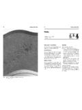
5 The resulting slag will thus consist of a complex liquid phase of oxides of iron, manganese, magnesium and silicon, silicates and sulfides plus a host of other complex compounds, which may include alumina, calcium oxides and sulfides, rare earth oxides and sulfides. Examples of these complex compounds include spinels, anorthites, hibonites, oldhamites and fosterites that are predominate in slags of base ductile and treated ductile irons. These components tend to be present in channel furnace Melting and holding applications. Table 1 illustrates the chemical analysis of a sample of Buildup taken from the inductor throat of a 30-ton vertical channel furnace used to melt base ductile iron. Table 1: Chemical composition of the slag Buildup from a 30-ton vertical channel furnace* Compound Percent Present MgO CaO MnO *Ref: DC Williams, Modern Castings, August, 1990 Melting Methods Coreless Induction Furnaces: The coreless induction furnace is a refractory-lined vessel with electrical current carrying coils that surround the refractory crucible.
6 A metallic charge consisting of scrap, pig iron and ferroalloys are typically melted in such a vessel. Electrical current in the coil forms a magnetic field, which in turn creates thermal energy, Melting the charge. The magnetic currents in the molten metal cause an intense stirring action, thus ensuring a homogenous liquid. During the Melting process, slag is generated from oxidation, dirt, sand and other impurities. Slag can also be generated from the scrap, erosion and wear of the refractory lining, oxidized ferroalloys and other sources. In a coreless induction furnace, slags normally deposit along the upper portion of the lining or crucible walls and above the heating coils. Figure 1 shows typical slag Buildup in a coreless induction- Melting furnace. 2 Figure 1: Typical slag Buildup in a coreless induction furnace (gray shaded areas) The hottest area of medium and high frequency coreless furnaces is at the mid-point of the power coil.
7 All areas of slag deposit will be at a much lower temperature than those occurring at the center of the coil. Slag can also be deposited in areas midway down the crucible lining, where insufficient metal turbulence from magnetic stirring occurs. Channel Furnaces: Another type of induction Melting furnace is the channel furnace. The configurations can be either vertical or drum type furnaces. In a coreless furnace, the power coil completely surrounds the crucible. In a channel furnace, a separate loop inductor is attached to the upper-body, which contains the major portion of the molten metal bath. In a coreless furnace, solid charge materials are melted using the induction field, whereas in a channel inductor, the induction field is used to superheat colder molten metal within the channel loop. A vertical channel furnace may be considered a large bull ladle or crucible with an inductor attached to the bottom.
8 Figure 2 illustrates how Insoluble components, such as slag, accumulate over time in the inductor loop or throat area. Buildup on the sidewalls of channel furnaces is also a common occurrence. Figure 2: Slag Buildup in the inductor and throat of a vertical channel furnace (gray shaded area) 3 (a) (b) Figure 3: Circulation and metal flow (shown by the arrows) in a (3a) single loop inductor and (3b) double loop inductor. Figure 3 illustrates circulation and metal flow through both single and double loop inductors. Not only can Buildup occur in the inductor loop and throat areas, but it also occurs in the stagnate or low metal flow areas immediately above the inductor loops. When this build occurs, insufficient metal flow between the inductor and uppercase limits heat transfer and interferes with the Melting operation. It is difficult to remove Buildup from the inductor loop or throat area.
9 Often a furnace operator will attempt to insert a steel rod or green wooden pole into the throat area even though accessibility is often severely limited. When significant accumulations of Buildup cannot be removed, the furnace is taken out of operation, the throat(s) are scraped clean and a newly lined inductor(s) is (are) installed. Normal inductor life may be as long as 18 months, however, if Buildup occurs, the useful life may be reduced to only a few months and in some cases, a few weeks. Pressure Pour Furnaces: Pressure pour furnaces are sealed holding/pouring furnaces blanketed with either an inert or air atmosphere and have an inductor attached to the bottom or side. Pressure pour furnaces are designed to hold liquid metal at a constant temperature for extended periods of time. When the furnace is pressurized, a stream of molten metal exits the vessel for mold filling.
10 These furnaces are not designed to melt metal. Circulation of liquid metal through the inductor loop provides the continuous superheating of liquid metal to keep a constant temperature of the remaining liquid metal in the furnace. Pressure pours are widely used in the processing of magnesium-treated ductile irons; they are usually pressurized with an inert atmosphere. As in a vertical channel furnace, slag often builds up in the inductor loop and throat areas (Figure 4). Slag Buildup also occurs along the sidewalls, effectively reducing the capacity of the vessel. Additional Buildup in the fill (receiver) siphon and pour (exit) siphon areas restricts metal flow rates into and out of the vessel. The choking or formation of restrictions in the siphons often is an ongoing battle that must be maintained throughout each heat or shift. Careful refractory selection and proper back-up insulation can help to lessen the degree of build-up that forms.