Transcription of CONTROLLERS FOR BD COMPRESSORS - Nova Kool
1 CONTROLLERS FORBD COMPRESSORSF lexible control settingsTOOLCOOL4 OPERATING INSTRUCTIONS (BD P-Housing)101N0212 Standard, 12/24 V DC 101N0340 AEO, 12/24 V DC101N0390 High Speed, 12/24 V DC101N0420 Solar, 10-45 V DC101N0510 AC/DC, 12/24 V DC, 100-240V AC101N0650 Automotive, 12/24 V DCWE HAVE MORE THAN 35 YEARS OF EXPERIENCE, DEVELOPING DIRECT CURRENT COMPRESSORS AND HELPING CUSTOMERS BENEFIT FROM THE OPPORTUNITIES OF MOBILE REFRIGERATION TECHNOLOGY. WITH A DEEP INSIGHT OF THE USAGE ACROSS VARIOUS APPLICATIONS WE HAVE EARNED A POSITION AS MARKET LEADER, WORKING WITH OEM-CUSTOMERS . THE STANDARDO peratingInstructions231. Introduction ..3 Applications ..3 Functions ..32. Technical data & specifications ..4 Technical data ..4 Specifications ..43. Wiring ..5 Wiring diagram ..5 Wiring diagram ..5 Wiring diagram ..5 Wire dimensions ..64. Menu overview ..7 User interface ..7 Operation ..75. Parameters ..8 Discription of parameters ..86. Battery protection.
2 9-10 Solar mode ..107. compressor speed ..11 compressor speed control modes ..12 Speed control Mode 1 ..12 Speed control Mode 1 ..12-13 Speed control Mode 2 ..14 Speed control Mode 3 ..14 Speed control Mode 4 ..14 compressor min. and max. speed protection ..158. Condenser fan ..169. Thermostat ..17 Thermostat type ..17 Electronic thermostat (NTC sensor) ..17 Mechanical thermostat ..17 Thermostat delays ..1710. Communication ..18 Lost communication ..18 Node Number ..18 Protection of Product information ..1912. Error and Event Log ..20 Actual Error ..20 Error Log ..20 Event Log ..2013. Inverter temperature (PCB) ..2114. Ordering ..2215. One wire/LIN MODBUS Parameter identification sheme ..24-2716. Installation of Install and configure software ..28-29 Install product key ..30 Connect network ..31-32 Ready to operate ..33 TABLE OF BD35F, BD35K, BD50F, BD80CN, BD100CN and compressor systems are mainly introduced for mobile refrigerators and freezers.
3 The operating conditions are Low/Medium/High Back Pressure (LBP/MBP/HBP). The system is able to operate in ambient temperatures up to +55 C (131 F).All electronic units are HST types (High Starting Torque) except 101N0420 (Solar). Typical applications for the electronic units are: Truck refrigerators and freezers Boat refrigerators and freezers Bus refrigerators and freezers Portable boxes Solar cabinets Agriculture RVThe 101N0212 controller is intended for a variety of DC-powered applications, while the 101N0650 is intended for automotive applications, where requirements to EMI and leakage current are is mainly intended for condensing units or systems with bigger load variations. It replaces the CONTROLLERS 101N0300/320/330. 101N0390 is intended for BD80F, BD100CN, and is intended for direct solar driven applications and replaces 101N0400 and 101N0410101N0510 is the new AC/DC unit and replaces 101N0500 The main functions of the CONTROLLERS are: Motor / compressor speed control Thermostat control (ON / OFF or electronic via NTC temperature sensor) ECO function to optimize compressor speed for minimum power consumption Fan control Error LED Communication interface Monitoring function Error & event log Battery protection functions Main Switch Log of specific parameters via Tool4 Cool software Optimization of specific parameters via PC software before commencing mass production Parameter setting via PC or resistors AEO (Adaptive Energy Optimizing) in selected models (101N0340, 101N0390 and 101N0420) is a list of key parameters of the new electronic units ( CONTROLLERS ).
4 2. TECHNICAL DATA &SPECIFICATIONSI nput V DC | 10-45 V DC (Solar unit) | 100 -240 V AC (AC/DC unit) operating temperature-10 to +55 CExternal fuse required15 A @ 12 V, A @ 24 V, slow blow typeStarting current15 A @ 12 V, A @ 24 VLeakage current 101N0212/340/390/420/510<= 4 mA @ 12 V, < 6 mA @ 24 VLeakage current 101N0650<= 150 A @ 12 V, < 170 A @ 24 VEMC approval 101N0212/340/390/420/510 Compliant to 2004/104/EC (e-marking)EC declaration 2004/108/ECCISPR 25 Class 1 CISPR 14 EMC approval 101N0650 Compliant to 2004/104/EC (e-marking)EC declaration 2004/108/ECCISPR 25 Class 4 in all operating modesCISPR 25 Class 5 except 80-82 Mhz radiated emission with 12 V supply at 3500 rpmNTC type to be connectedEpcos M800/5 KFan output5 W, nominal voltage 12 V Use a fan with over/undervoltage protection A 12 V fan must also be used in 24 V systemsTest nameStandardConditionsTemperature shockVW 801 01: 2009-03 sec +105 C, 10 sec, 75 cyc/min., 300 cycVibrationFreightliner Eng Std 49-000855-500 Hz, 4 g, X-Y-Z axis, 3x3 h eachSalt MistVW 801 01: 2009-03 sec , 1 of 8 hours running, 6x8 h spray on/16 h off, 5 % NaCL, 35 C, 1-2 ml/80 cm3/hCorrosionASTM G85 Annex % NaCL + % ammonia sulphate, 35 C, 6 h of 1 h on/1 h off repeatedGas exposure6h, 75 % RH, % H2S + % SO3 Thermal cycling with humidityEN60068-2-35 test Db-10/+55 C, 97 % RH, 3 weeks, compressor running intermittingStorageVW 801 01: 2009-03 sec +90 C 96 h, -40 C 24 hIP testEN 60529 Edition 2001-02 Min.
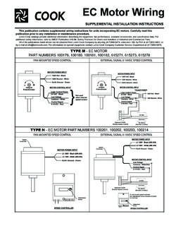
5 IP 20 Free fallIEC 60068-2-321 m, concrete, 2 times 2 sidesThermography0/60/60 C max. speed, solder below 110 C, components acc. Secop derating guidelineThermal performanceSteady state: 15/60/60 C @ 2000, 10/60/60 C @ 2500, 5/60/60 C @ 3000, 0/60/60 C @ down, 5 min. without cutout: 15/70/60 C @ 2000, 15/70/60 C @ diagram101N0212, 101N340, 101N0390, 101N0650 compressor control units have the following connections:-, + Main supply voltage. Nominal voltage 12 V DC and 24 V DC, range: to 32 V DC.+, F Fan connection, max. 5 W, connect always 12 V fan (even in 24 V systems).D/I: Connect either an Error LED between + and D/I for a simple error indication. The Error LED will be driven with 10 mA constant current. Or connect communication interface (Tool4 Cool gateway or customer controller like display) between D/I and C. P, C Connect a battery protection resistor to select the required battery cut out value. See table at chapter 6, Battery programming, on page +T Connect either a mechanical thermostat, a mechanical thermostat in series with a speed programming resistor or a NTC temperature sensor.
6 See chapter 7, Speed control modes on page , N Main supply voltage, voltage range 100-240 V AC 50/60 HzA, C Lamp connection (max. 5 W, connect always 12 V)The above mentioned maximum wire length ensures sufficient low voltage drop during start and operation. Thinner wires may cause unintended low voltage battery cut-outs due to low voltage at the electronic unit, despite the voltage at the battery still being in an acceptable length*12 V DC operationMax. length*24 V DC operationAWGG augeCross * Length between battery and electronic unitWire dimensions ACCross section min. mm2 or AWG 18101N0212, 101N340, 101N0390, 101N0420, dimensions101N0212, 101N340, 101N0420, 101N0510, 101N0650 Wire dimensions101N0390 SizeMax length*12 V DC operationMax. length*24 V DC operationAWGG augeCross * Length between battery and electronic unitOperatingInstructions67 Operation of the compressor control unit can be done through the Secop PC software Tool4 Cool An example of the menu structure is shown below.
7 It may vary depending on the controller model. On the following pages each separate menu is explained in installation and operation of Tool4 Cool , please refer to Chapter 15 Installation of the software on page Tool4 Cool software enables the user to observe and document certain aspects of the compressor operation via the controller . The output of the software is in the form of data logs and plots. Using Tool4 Cool the user can also change the settings of the controller parameters, and copy settings from one controller to another. MENU OVERVIEWO peratingInstructions89 Main Switch FunctionIn order to start and stop the compressor the Main Switch can be set to ON or making an interface with custom design electronics via Modbus must be able to control the CCU ON/OFF via the Main Switch (CCU = compressor Control Unit).ON: All functions are : All main functions are inactive, however Battery monitoring active NTC temperature sensor monitoring active PCB inverter temperature monitoring activeSettingsBeside the Main Switch parameter a default main switch parameter is available.
8 This parameter defines, how the main switch will be set after a power supply interruption. For standalone systems without a customer specific controller ( display) it s recommended to have this default main switch set to 1 (ON) which is also the default. This way the unit will automatically continue to run after a power systems using a customer specific controller ( display), it should be set to 0 (OFF) to ensure, that the COMPRESSORS stays off even after a power down/up, if the communication line is interrupted. NameDefaultMax. valueMin. valueStepUnitMain switchONONOFF1-Default main switchONOFFON1-Discription of parameters5. PARAMETERSO peratingInstructions89 The battery protection prevents permanent damage to the battery by setting range is 9-17 V DC for 12 V DC systems, and 19 to 27 V DC for 24 V DC cut out values and cut in differences can be set individual for 12 V systems and 24 V systems. Battery protection function is disabled in Solar controller 101N0420 (fixed range 10 to 45 V DC).
9 If the voltage remains below the cut-out voltage for the time specified in the parameter Cut-out delay (default 3s), compressor and fan are and fan are stopped immediately, if the voltage drops below 8 V in 12 V systems and below 18 V in 24 V systems (critical stop).If Solar mode is enabled, the electronic will be able to run over the entire input voltage range (9-32 V), without stopping between 12 V and 24 V are V valueMin valueStepUnitBattery cutout level 12 V cut-in diff. 12 V cut-out level 24 V cut-in diff. 24 V Solar mode on/offDisableEnableDisable--Cutout delay36001 Seconds6. BATTERY PROTECTION ONOFFOFFONA larm stateComp. stateCut-out levelCut-in levelMax limit 32 V DC0-60 sec 60-120 sec Battery ProtectionCritical stop 8 V/18 V DC(Restart delay)(Cut-outdelay)(Voltage failure)OperatingInstructions1011 MeasurementsIn order to let the compressor run on solar panels, the solar mode should be enabled. The solar mode can be enabled either with Tool4 Cool or with a 220 kOhm resistor between C and P.
10 With solar mode enabled, the battery protection settings will not stop the compressor between 12 V and 24 V voltage range, but let it run over the entire voltage range from 9 to 32 V above mentioned is not valid for dedicated Solar controller 101N0420 which can run from 10 to 45 V program the battery cut out value, either Tool4 Cool can be used or a resistor can be connected between C and P. See R2 in chapter and , wiring diagrams on page 5. Not valid for Solar controller 101N0420 (10 to 45 V DC)NameDefaultMax valueMin valueStepUnitBattery Solar mode programming resistorNameNoteUnitVoltage cut-out levelOnly show in Solar ModeVoltBattery cut-in levelIn Solar Mode change text to voltage cut-in levelVoltSupply voltageMeasured on + and - terminalsVoltResistor (R2) k 12 V cut-out [V]12 V cut-in [V]12 V max. [V]24 V cut-out [V]24 V cut-in [V]24 V max. [V] speed and thereby the capacity of the compressor is set using the Requested speed parameter. During start up, the compressor runs at a lower speed, Start speed (fixed 2500 rpm) , than Requested speed.