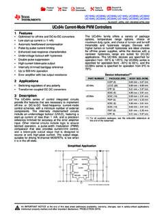
Transcription of .CONVERTERS OPTIMIZED FOR OFF-LINE AND DC …
1 UC2842/3/4/5UC3842/3/4/5 October 1998 CURRENT MODE PWM FOR OFF-LINE AND DC TO START-UP CURRENT (< 1 mA).AUTOMATIC FEED FORWARD CURRENT LOAD RESPONSE LOCKOUT WITH PULSE CURRENT TOTEM POLE TRIMMED BANDGAP KHz ROERROR AMPDESCRIPTIONThe UC3842/3/4/5family of control ICs provides thenecessary features to implement OFF-LINE or DC toDC fixed frequency current mode control schemeswith a minimal external parts count. Internallyimple-mentedcircuits include undervoltagelockout featur-ing start-up current less than 1 mA, a precision ref-erence trimmed for accuracy at the error amp input,logic to insure latched operation, a PWM compara-torwhich also providescurrent limit control,and a to-tem pole output stage designed to source or sinkhigh peak current. The output stage, suitable fordriving N-Channel MOSFETs, is low in the between members of this family are theunder-voltage lockout thresholds and maximumduty cycle ranges.
2 The UC3842 and UC3844 haveUVLO thresholds of 16V (on) and 10V (off), ideallysuited OFF-LINE applications The correspondingthresholds for the UC3843 and UC3845 are Vand V. The UC3842 and UC3843 can operateto duty cycles approaching 100%. A range of thezero to < 50 % is obtained by the UC3844 andUC3845 by the additionof an internal toggle flip flopwhich blanks the output off every other clock DIAGRAM(toggle flip flop used only in U3844 and UC3845)MinidipSO14 1/11*All voltages are with respect to pin 5, all currents are positive into the specified CONNECTIONS(top views)SO14 MinidipORDERING NUMBERSTypeMinidipSO14UC2842UC3843UC2844 UC2845UC2842 NUC2843 NUC2844 NUC2845 NUC2842 DUC2843 DUC2844 DUC2845 DUC3842UC3843UC3844UC3845UC3842 NUC3843 NUC3844 NUC3845 NUC3842 DUC3843 DUC3844 DUC3845 DABSOLUTE MAXIMUM RATINGSSymb olParamet erV al ueUnitViSupply Voltage (low impedance source)30 VViSupply Voltage (Ii < 30mA)Self LimitingIOOutput Current 1 AEOO utput Energy (capacitive load)5 JAnalog Inputs (pins 2, 3) to Amplifier Output Sink Current10mAPtotPower Dissipation at Tamb 50 C (minidip, DIP-14)1 WPtotPower Dissipation at Tamb 25 C (SO14)
3 725mWTstgStorage Temperature Range 65 to 150 CTLLead Temperature (soldering 10s)300 CTHERMAL DATAS ymbolDescriptionMinid ipSO14 UnitRth j-ambThermal Resistance CUC2842/3/4/5-UC3842/3/4/52/11 ELECTRICAL CHARACTERISTICS(Unless otherwise stated, these specifications apply for -25 < Tamb<85 C for UC2824X; 0 < Tamb<70 C for UC384X; Vi= 15V (note 5); RT= 10K; CT= )SymbolParameterTest ConditionsUC284 XUC384 XUnitMin. Typ. Max. Min. Typ. SECTIONVREFO utput VoltageTj=25 CIo= VREFLine Regulation12V Vi 25V6206 20mV VREFLoad Regulation1 Io 20mA6256 25mV VREF/ TTemperature Stability(Note 2) CTotal Output VariantLine, Load, Temperature (2) Noise Voltage10Hz f 10 KHz Tj=25 C(2)5050 VLong Term StabilityTamb= 125 C, 1000 Hrs (2)5255 25mVISCO utput Short Circuit-30-100 -180-30-100 -180mAOSCILLATOR SECTIONfsInitial AccuracyTj=25 C (6)475257475257 KHzVoltage Stability12 Vi StabilityTMIN Tamb TMAX(2)55%V4 AmplitudeVPIN4 Peak to AMP SECTIONV2 Input VoltageVPIN1= Bias AAVOL2 Vo 4V65906590dBBUnity Gain Bandwidth(2) Voltage Rejection12V Vi 25V60706070dBIoOutput Sink CurrentVPIN2= VPIN1= Source CurrentVPIN2= VPIN1= ;RL= 15K to Ground5656 VVOUTLowVPIN2=.
4 RL= 15K to Pin SENSE SECTIONGVGain(3 & 4) Input SignalVPIN1= 5V (3) Voltage Rejection12 Vi 25V (3)7070dBIbInput Bias Current-2-10-2-10 ADelay to Output150300150300nsOUTPUT SECTIONIOLO utput Low LevelISINK= High LevelISOURCE = TimeTj=25 CCL= 1nF (2)5015050150nstfFall TimeTj=25 CCL= 1nF (2)5015050150nsUC2842/3/4/5-UC3842/3/4/5 3/11 Notes :2. These parameters, although guaranteed, are not 100% tested in Parameter measured at trip point of latch with VPIN2= Gain defined as : VPIN1A=;0 VPIN3 V VPIN35. Adjust Viabove the start threshold before setting at 15 Output frequency equals oscillator frequency for the UC3842 and frequency is one half oscillator frequency for the UC3844 and CHARACTERISTICS(continued)SymbolParamete rTest ConditionsUC284 XUC384 XUnitMin. Typ. Max. Min. Typ. LOCKOUT SECTIONS tart ThresholdX842 Operating VoltageAfter Turn-onX842 SECTIONM aximum Duty CycleX842/393971009397100%X844/546485047 4850%Minimum Duty Cycle00%TOTAL STANDBY CURRENTIstStart-up Supply CurrentVPIN2=VPIN3=0V11201120mAVizZener VoltageIi= 25mA3434 VUC2842/3/4/5-UC3842/3/4/54/11 Figure 1 :Error Amp amp can source orsink up to 2 :Under Voltage Under-Voltage Lockout, the output driver isbiased to sink minor amounts of current.
5 Pin 6should be shunted to ground with a bleeder resistorto prevent activating the power switch with extrane-ous leakage 3 :Current Sense Circuit .Peak current (is) is determined by the VIS max RSA small RC filter may be required to suppress switch 5 :Deadtime vs. CT(RT>5K ). RT>5K f=RTCTF igure 7 :Output Saturation 6 :Timing Resistance vs. 8 :Error Amplifier Open-loop 9 :Open Loop Test peak currents associatedwith capacitive loadsnecessitate careful grounding techniques. Timingand bypass capacitors should be connected closeto pin 5 in a single point ground. The transistor and5K potentiometerare used to sampletheoscillatorwaveform and apply an adjustable ramp to pin 10 :Shutdown of the UC2842 can be accomplished bytwo methods ; either raise pin 3 above 1V or pull pin1 below a voltage two diode drops above method cause the output of the PWM com-parator to be high (refer to block diagram). ThePWM latch is reset dominant so that the output willremain low until the next clock cycle after the shut-down condition at pins 1 and/or 3 is removed.
6 In oneexample, an externally latched shutdown may beaccomplishedby addingan SCR which will be resetby cycling Vibelowthe lower UVLO thispoint the reference turns off, allowing the SCR to 11 : OFF-LINE Flyback Supply Specifications1. Input Voltage :95 VAC to 130 VAC(50 Hz/60 Hz)2. line Isolation :3750 V3. Switching Frequency :40 KHz4. Efficiency @ Full Load : 70 %5. Output Voltage :A. + 5 V, 5 % : 1 A to 4 A loadRipple voltage : 50 mV P-P + 12 V, 3 % : A to A loadRipple voltage : 100 mV P-P 12 V, 3 % : A to A loadRipple voltage : 100 mV P-P 12 :Slope fraction of the oscillator ramp can be resistivelysummed with the current sense signal to provideslope compensation for converters requiring dutycycles over 50 %.Note that capacitor, C, forms a filter with R2to su-press the leading edge switch (typ.)D (1) (1) (1) D and F do not include mold flash or protrusions. Mold flash orpotrusions shall not exceed (.)
7 006inch).OUTLINE ANDMECHANICAL DATA(max.)UC2842/3/4/5-UC3842/3/4/59/11 Minidip ANDMECHANICAL DATAUC2842/3/4/5-UC3842/3/4/510/11 Information furnished is believed to be accurate and reliable. However, STMicroelectronics assumes no responsibility for the conse-quences of use of such information nor for any infringement of patents or other rights of third parties which may result from its use. Nolicense is granted by implication or otherwise under any patent or patent rights of STMicroelectronics. Specification mentioned in thispublication are subject to change without notice. This publication supersedes and replaces all information previously supplied. STMi-croelectronics products are not authorized for use as critical components in life support devices or systems without express writtenapproval of ST logo is a registered trademark of STMicroelectronics 1998 STMicroelectronics Printed in Italy All Rights ReservedSTMicroelectronics GROUP OF COMPANIESA ustralia - Brazil - Canada - China - France - Germany - Italy - Japan - Korea - Malaysia - Malta - Mexico - Morocco - The Netherlands -Singapore - Spain - Sweden - Switzerland - Taiwan - Thailand - United Ki ngdom - datasheet has been download for electronics components.