Transcription of COOLING LARGE VARIABLE FREQUENCY DRIVES - TMEIC
1 COOLING LARGE VARIABLE FREQUENCY DRIVESThe heat contribution by the converter and inverter sections is approximately 75% of the VFD system heat loss. Typically the VFD system itself is 96 97% efficient. The input isolation transformer is typically 98 99% efficient. VFDs that permit component splitting may offer more packaging and COOLING alternatives for example, being able to locate the input transformer separately (or outdoors) from the COOLING In performing its critical operation, a well-selected VFD COOLING system provides three major functions: 1. Reliably removes the heat from the power semiconductor devices in the inverter, converter, and from their auxiliary components. 2. Maintains the overall VFD temperature for long system life. 3. When optimized, allows the VFD to deliver rated power with the smallest equipment the present time, there are two methods of COOLING a VARIABLE FREQUENCY drive, air COOLING and liquid COOLING .
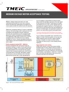
2 Air-Cooled VARIABLE FREQUENCY Drive VFD air- COOLING works on the principle that heat transfers from hot devices and component surfaces to the mass of air flowing over or past them. Most air-cooled VFDs use fans to force air through the VFD to dissipate heat. Figure 3 shows a front view of an air-cooled VFD. APPLICATION EDGE VOLUME 1, ISSUE 4 Medium-voltage VARIABLE FREQUENCY DRIVES (VFD) are available in power ranges from 200 to 100,000 kW. High efficiency over a wide speed range, ease of installation, low maintenance and other factors have contributed to increased application of VFDs. Small VFDs (200 5000 HP) are typically air-cooled. As power ratings increase above 5000 HP, liquid COOLING is more common because air COOLING is not as economical, and liquid COOLING reduces the footprint of these higher power DRIVES (see Figure 1).
3 Sources of Heat in a VFD SystemFigure 2 shows the basic building blocks of a VFD and motor system. All building blocks shown below are not necessarily needed for every system. Figure 2. Basic building blocks of VFD systemAs shown in Figure 2, the major sources of heat in a VFD are: 1. Input isolation transformer 2. AC-to-DC Converter 3. DC Link (energy storage) 4. DC-to-AC Inverter Figure 3. Typical air-cooled VFDs and air flowWarm Air ExhaustCooling Air InFigure 1. Power vs. voltage for air- and liquid-cooled VFDsAdvantages Air COOLING of VFDs is simpler than liquid COOLING and has the following advantages: 1. An air-cooled VFD COOLING system is self-contained. There are no pumps, hoses, piping, filters, deionizers, or heat exchangers. 2. Servicing/support of the client s HVAC system is more readily available.
4 3. When applied for starting duty only, smaller VFDs can often be applied to LARGE motors on a short time Corresponding disadvantages of an air-cooled VFD include: 1. Air-cooled units usually have a larger footprint compared to a similar size liquid-cooled VFD. 2. Blower fans for COOLING the VFD typically have noise levels of 79 82 dB(A) at 1 meter from drive. 3. The VFD area must be kept clean, dry and free of dust. Inspection and maintenance of air filters may be required. 4. HVAC power requirements for COOLING the heated air rejected from the drive may be higher than the pumping power required for liquid-cooled VFDs. This should be considered when doing life cycle cost Major maintenance items on air-cooled VFDs include: 1. Inspection and cleaning of air filters.
5 In most VFDs, this can be done during operation. 2. Inspection and verification of the HVAC operation for proper COOLING , dust or contaminants buildup, and other visible problems. 3. Verify that the VFD location continues to maintain an atmosphere free from dust, moisture and VARIABLE FREQUENCY Drive Liquid-cooled VFD COOLING systems are more complex than their air-cooled VFD counterparts. Liquid-cooled systems are engineered for the installation, considering temperature ambient(s), COOLING water availability and redundancy level required. Principles of Liquid- COOLING Liquid-cooled VFDs include a pump COOLING panel consisting of electronic controls, electrical pumps and mechanical equipment to move the liquid through the VFD. This pump COOLING panel has a similar role as the industrial fans that draw air into and through air-cooled VFDs.
6 The liquid used in most VFDs is either deionized water or a mixture of deionized water and glycol for low ambient temperature applications. The deionization is required to maintain a low electrical conductivity of the fluid, a requirement imposed by the high voltages that appear on the heat-producing Systems Configurations There are two major configurations of VFD liquid COOLING systems shown in Figure 4. 1. Liquid-cooled VFDs that have an internal liquid-to-liquid heat exchanger, Figure 4a. 2. Liquid-cooled VFDs that are outfitted with an outdoor liquid-to-air heat exchanger for heat dissipation, Figure 4. VFD liquid COOLING system configurations In the liquid-to-liquid system, Figure 4a, the COOLING loop A is always a closed loop carrying deionized fluid internal to the VFD through a liquid-to-liquid heat exchanger.
7 The second liquid COOLING loop (Loop B) carries the plant COOLING water, which takes away the heat picked up from the internal the liquid-to-air system, Figure 4b, the COOLING loop A and the COOLING loop B are actually one common loop carrying deionized fluid. The fluid path passes through the hot drive parts, through the pump panel and out to the external liquid-to-air heat exchanger where it is cooled and returned. Because the heat exchanger is often located outdoors, the COOLING fluid must be tolerant of the outdoor ambient temperatures. The fluid may need to include a glycol mixture with the water to inhibit freezing. COOLING System Arrangement DetailsLiquid-cooled VFDs as shown in Figure 4a are fitted with an internal liquid-to-liquid heat exchanger. The two COOLING loops in the system are the VFD loop (Loop A), which is the deionized liquid loop, and the plant liquid loop (Loop B).
8 A specific plant liquid VFD inlet temperature range is required for optimum heat transfer by the COOLING system. Liquid-to-liquid systems are less expensive than liquid-to-air systems and more compact. However, liquid-to-liquid systems do require facility COOLING water to be brought to the VFD. They are best applied at sites where COOLING water is also used to cool other plant shown in Figure 4b, VFDs with liquid-to-air heat exchangers typically use outdoor radiator type forced air-cooled exchangers to transfer the heat from the liquid. This is a similar arrangement to a car radiator. One of the benefits is that no plant COOLING liquid is required to cool the VFD, making it a very attractive solution for remote VFDs or facilities with no available COOLING water. Liquid-to-air systems are more expensive than liquid-to-liquid designs.
9 The higher costs include the exchanger itself, the space and mounting pad for the exchanger, piping and the ongoing expense of the fan operation. Operation depends on the outdoor ambient temperature being cool enough to transfer the heat efficiently. In practice, ambient temperatures of up to 40 C can easily be accommodated by this type of system higher ambient temperatures may require de-rating of the VFD Components, System Details and FunctionsVFD COOLING systems typically include the following equipment and instrumentation: 1. Motor driven pumps 2. Control system with instrumentation and sensors for conductivity, temperature, pressure and flow 3. Coolant reservoir 4. Heat exchanger 5. Deionizer cartridge and filter 6. Pipes, valves , and actuators Figures 5a and 5b show typical liquid COOLING system process and instrumentation diagrams.
10 This may vary from manufacturer to manufacturer, and even from drive to drive for a particular manufacturer. However, the general concept remains the same. Liquid is passed through the components at various points within the drive that are in contact with the power semiconductors, diodes and other heat-generating devices. As the VFD delivers power, heat is transferred from the devices to the hot surfaces and then to the liquid flowing through the pump. Then this hot liquid is pumped from the VFD through the heat exchanger. Depending on the selection, heat from the hot liquid is either transferred to the plant COOLING water as shown in Figure 5a, or to the air Figure 5a. VFD liquid-to-liquid COOLING systemFigure 5b. VFD liquid-to-air COOLING systemas shown in Figure 5b. The cooled liquid then flows back to the VFD and the whole process is repeated.