Transcription of Counterounter Point - Wells Vehicle Electronics
1 But they are also used in many distributorlessignition systems (DIS) to determine theposition of the crankshaft and camshaft. This is because the engine computer needs to know where the number one cylinder is assoon as the engine is cranked. As soon as the all-important sync-pulse is detected, the ignition module can start firing the plugs in the correct sequence. This alsoallows injector timing to be matched to the firing order in engines with sequentialfuel Effect Sensors are sometimes referred toas switches rather than sensors because ofthe on-off digital voltage signal theyproduce. Unlike magnetic sensors thatproduce an alternating current (AC) signalwhich varies in voltage with speed, HallEffect Sensors produce a constant voltagesignal that can change abruptly frommaximum voltage to nearly zero andback again regardless of engine produces a square wave outputsignal that can be easily used by theonboard computer for timing WORKINGSA typical Hall Effect Sensor has three wires orterminals: one for ground, one for supply orreference voltage and one for the outputsignal.
2 To produce an output signal, a HallEffect Sensor must be supplied with areference voltage from the Vehicle s onboardcomputer (which may be 5 to 12 voltsdepending on the application). The supplyvoltage is necessary to create the switchingeffect that takes place inside the operating principle upon which HallEffect Sensors are based (and so named) dates WHAT S INSIDE:WHAT S INSIDE:Understanding Hall Effect 1 / Wells Earns QS-9000 Status at all 1 / Requests for Subscriptions Top 25, 1 / FINE 3 /QUALITY POINTS: Wells Training Seminars for 3 / HOT OFF THE WIRE: Wells Expands Professional Gold 4 / Publisher s 4 Understanding HallEffect SensorsCounterCounterPointTHE ELECTRONIC, DIAGNOSTIC AND DRIVEABILITY 3 Issue 1, January1999 Volume 3 Issue 1, January 1999continued on page 2continued on page 2 Wells EarnsQS-9000 Status at all FacilitiesWELLS EarnsQS-9000 Status at all FacilitiesRequests forSubscriptionsTop 25,000 Wells Manufacturing Corp.
3 Has earned QS-9000 quality compliance at all four of thecompany s facilities. QS-9000 is the toughest quality standard in theautomotive industry, said Wells President William Allen. For Wells to earn the recognitioncompanywide assures our customers that they are getting the best parts backed by the best service available. QS-9000 is a stringent and uniform quality standardestablished by the Big Three automakers to ensure thatall their suppliers meet the highest quality and maintaining QS-9000 status is ademanding process, which can take thousands ofman hours of preparation. Companies must undergotwice-a-year audits to maintain the quality in 1996 became the first and thus far onlyfull-line manufacturer of ignition components to earnQS-9000 compliance for the manufacture of electronicengine management systems, charging systems and year, Wells also earned QS-9000 compliance for its second manufacturing facility in Fond du Lac, Wisconsin, one in Reynosa, Mexico and itsdistribution complex in Centerville, forSubscriptionsTop 25,000In its first year, Wells Counter Pointquarterlynewsletter generated more than 25,000 subscriptionrequests from technicians.
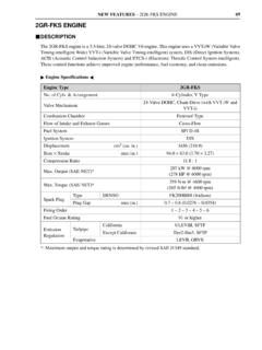
4 We started Counter Point to provide additional supportfor technicians, said Gavin Spence, Wells vicepresident of sales. We re gratified that so many ofthem have found it a valuable informational tool. Anyone wanting a new subscription should fill out theform on Page 4 of this issue. Those who alreadysubscribed will automatically receive future EFFECT PICK-UPSHUTTER BLADEDISTRIBUTOR BOWLHall Effect Sensors are used in many ignition system distributors to trigger the primary circuit (fire the coil) and to monitor engine from page 1continued from page 1 Understanding Hall Effect Sensorsback to 1879 when Edwin H. Hall, anAmerican scientist, discovered a new electricalphenomenon. When he applied an electriccurrent to a piece of metal inserted betweentwo magnets, it created a secondary voltage inthe metal at a right angle to the appliedvoltage. The discovery didn t have muchpractical use at the time, but it turned out tobe just the thing that future engineers wouldneed to create a switching device capable ofproducing an efficient on-off square-wavevoltage signal.
5 The Hall Effect was adapted so the voltage change would occur in asilicone chip placed at a right angle to amagnetic a metal blade passes through the airgap between the magnetic field and siliconchip, it blocks the magnetic field and causesthe chip s output voltage to suddenly drop tozero. With additional circuitry, the sensor canbe made to do just the opposite: to produce avoltage signal when the blade enters themagnetic field. Additional circuitry regulatesthe supply voltage to the chip and amplifiesits voltage output. In an automotive ignitionsystem, shutter blades are mounted on thedistributor shaft, rotor, crankshaft pulley orcam gear so the sensor can generate a triggerand/or position signal as the crankshaftrotates. In some applications, a notch in apulley, a gear tooth or even a rotatingmagnetic button serves the same purpose asthe shutter blade to disrupt the sensor smagnetic window and trip the Hall Effect Sensor may be normally on or off depending on how its circuitry isdesigned.
6 The normally on variety (such asGM crank position sensors) produces a steadyvoltage output when the magnetic window isunobstructed and no blades are passingthrough it. The voltage output drops to nearzero when a blade enters the magnetic windowand blocks the field. The Profile Ignition Pick-up (PIP) and Cylinder Identification (CID)Hall Effect Sensors found in Forddistributorless ignition systems work in theopposite manner. When the shutter bladepasses through the window and blocks themagnetic field, the sensor s internal electronicsswitch the sensor s output signal from nearzero (off ) to maximum voltage (on).TROUBLESHOOTINGS ensor problems can be caused by wiringfaults, loose or corroded connectors, or arcingthat damages the internal electronic are several ways to troubleshoot HallEffect Sensors. One is to use a self-powered indicator light type of Hall Effect Tester thatflashes when the sensor s output signalchanges.
7 If the sensor is being tested on thevehicle, simply plug the tester into the sensor,then crank the engine and observe theindicator light. It should wink on and offwhile the engine is cranking. If the sensor isbeing tested off the Vehicle , plug the tester intothe sensor connector and observe the indicatorlight. It should remain on steadily. Theninsert a metal blade into the sensor s magneticwindow (air gap). The indicator should go off while the blade is in the window, thenwink back on when the blade is removed. No change would indicate a faulty sensor problems can be caused byseveral things: The sensor must have the proper referencevoltage (VRef ) power supply from the computer. If the sensor is not receiving the required voltage, it won t work. Measurethe supply voltage between the sensor s power supply wire and ground (use the engine block for a ground, not the sensor sground circuit wire).
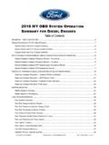
8 If you don t see the specified voltage, check the sensor s wiringharness for loose or corroded connectors. The sensor s ground circuit must be in good condition. A poor ground connection will have the same effect on the sensor s operation as a bad VRef supply. Measure the voltage between the sensor s ground wire and the engine block. If you see more than volts, the sensor has a bad ground the sensor has power and ground, the nextthing to check would be sensor output. Thevoltage output signal should switch back andforth from maximum to near zero as theengine is cranked. No change would indicate a faulty sensor. Watching the sensor s voltage output on an oscilloscope is a good way to spot problems that mightescape normal diagnosis. You should see anice, sharp square wave pattern that goes frommaximum to near zero (or vice versa) everytime the sensor switches on and off. The sync pulse signal from a crank/cam positionsensor should also stand out and be readilyapparent in the waveform.
9 If you see roundedcorners, spikes, excessive noise or variations in amplitude from one pulse to the next, the erratic operation of the sensor may becausing the computer to miss signals or pick up false the case of cam/crank sensors, the HallEffect Sensor must be properly aligned withthe interrupter ring or shutter blade togenerate a clean signal. A worn or stretchedtiming chain as well as cam walk can affectthe sensor s output. Any contact between themoving parts and sensor can cause idleproblems as well as sensor damage. A failureof a crank position sensor usually causes theengine to quit because the reference signal for the ignition and fuel injectors is you re testing an electronic ignition system with a Hall Effect Pick-up in thedistributor, you can insert a steel feeler gaugeor pocket knife blade, etc. into the sensorwindow to see if it fires the ignition the magnetic window in a HallEffect Sensor should have the same effect asopening the points in a breaker Point ignitionsystem.
10 Don t forget to turn the ignitionswitch on before making this test. Also, makesure the spark has a proper path to ground viaa spark gap older Chrysler Hall Effect IgnitionSystems, the shutter blades under the rotormust be properly grounded to produce a cleansignal. Use an ohmmeter to check continuitybetween the shutter blades and distributorshaft. If the blades are not grounded, thesensor will check out ok but won t produce agood signal when the engine is cranked withthe rotor in place. On Ford applications withThick Film Integrated (TFI) ignitiondistributors, the Hall Effect Signal is calledthe Profile Ignition Pick-up (PIP) signal. Corroded connectors between the Hall EffectPIP unit in the distributor and the TFImodule on the distributor housing arecommon. Replacing the sensor isn t as easy on these applications because you have to R&R the distributor EFFECT SQUARE WAVE SIGNALVOLTAGE REGULATORPOWERSIGNALMAGNETAMPLIFIERGROUN DHALL EFFECT TESTERHALL EFFECT SENSORMETAL BLADESWITCHED SIGNALHALL EFFECT SENSOR TESTING PROCEDUREWELLS Manufacturing Corp.