Transcription of Cranking MotorsOr “Starters” To The Rest Of Us
1 Cranking Starters To The Rest Of Us1 Cranking Starters To The Rest Of should come as no surprise that the theory of how a starter works is much the same as howthe generator works. This means all the time and effort you spent learning how a generator workswill not be wasted. We, of course, know that a starter has only one job, to crank over the engine sothe engine can start. Let s look at what is the starter , internally, is built much like a generator. Inside you will find an armature, pole shoes(magnets) and field coils. You will also find a commutator end of an armature, and brushes just like WE CAN TALK ABOUT THE DIFFERENCES, WE NEED TO TALK ABOUTMOTOR PRINCIPLES, OR THE THEORY OF HOW A starter MOTOR you will remember the armature and pole shoe arrange-ment we had for our generator, to that we are going to add a horseshoe shaped magnet.
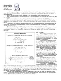
2 With this arrangement there will betwo magnetic fields, one created by the conductor current and onecreated by the horseshoe magnetic lines leave the north pole and enter at thesouth pole (trust me on this) the direction of the current of thehorseshoe magnet would be upwards. The conductor current wecreate with a rotating magnetic field is in the clockwise direction,just as it did in the result is a heavy concentration of magnetic current onthe left-hand side of the wires, where the two magnetic currentscome together and become Starters To The Rest Of Us2A basic motor is illustrated. A loop of wire is located between two iron pole pieces and isconnected to two separate commutator segments, or bars.
3 Riding on the commutator barsare two brushes, which are connected to the batter and to the windings located over the polepieces. With this arrangement, current flow can be traced from the battery through the polepiece windings to a brush and commutator bar, through the loop of wire to the other commu-tator bar and brush, and then back to the battery. The resulting magnetic field imparts a turn-ing or rotational force on the loop of wire as magnetic current left over on the right-hand side is just the opposite of the conductorcurrent, so they will cancel each other strong current of the horseshoe magnet and the strong current from the conductor willcombine. Because the weaker currents on the right-hand side have canceled each other out, theleft-hand current is where the Cranking motor will actually get its Cranking THAT WE KNOW HOW THINGS WORK, LET S ADD A COMPLETE ARMATUREAND FIELD COILS TO OUR starter MOTOR.
4 WE CAN THEN DEVELOPTHE CURRENT FOR A COMPLETE starter of the main differences of a starter is that it requires a lot of current for a short time, asopposed to a generator, which works with a small amount of current over a longer period of of this, there are two types of field coils used in starters. They are series and current that flows through a series coil also flows through the armature windings. The currentthat flows through a shunt coil bypasses the armature and flows directly back to the AND FIELD ASSEMBLYThe frame and field assembly consists of field coil windings assembled over iron pole pieces which are at-tached to the inside of a heavy iron frame. The iron frame and pole shoes not only provide a place onto whichthe field coils can be assembled, but also provide a low reluctance, or low resistance path for the magnetic fluxproduced by the field number of wiring diagrams showing the various types of field coil connections are illustrated.
5 By tracing thecurrent flow through the windings, and by using the Right Hand Rule, it is seen that the polarity of the face ofeach pole shoe over which the coil is wound alternators around the field frame. That is, the polarities alternatenorth, south, north and shunt coil can be easily identified because of its direct connection to ground. Shunt coilswill also be made up of a number of turns of smaller wire, just like in a of the extra current necessary forthe starter to do its job, a starter will need at leasttwo sets of brushes. Sometimes three sets arerequired for heavy-duty shunt coil does for a starter , just like itdoes for a generator (controls the output).
6 As welearned about generators, if there is not somecontrol of the output, overcharging will occur anddamage to the electrical system will a starter , if the electrical current outputis not regulated, the starter motor will spin out ofcontrol, causing damage to itself, just like a gen-erator. So the job of the shunt coil is to control the output of the Starters To The Rest Of Us3 Cranking Starters To The Rest Of Us4 The series coils have the job of increasing the current output of the pole shoes, much like thefield coils in a generator. The turning force or torque of a starter is determined for the most part bythe current available to the series coils, and their position inside of the starter , along with batterycable size, battery capacity, and current carrying capacity of the motor some applications it is necessary to add an equalizer bar across two or more brushes toequalize the voltage at the , WE KNOW THE starter IS LIKE A MOTOR.
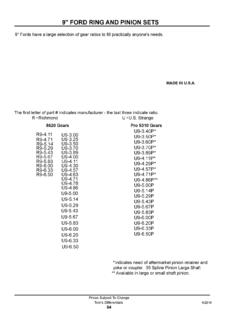
7 NOW HOW DO WE GET THE MOTOR TO CRANK OVER THE ENGINE?This is done through the motor drive, or starter bendix as it is commonly called. The motordrive is assembled on the armature shaft and is the part that actually comes into contact with theflywheel (the big gear on the back of the motor), and cranks over the engine. There are a number ofdifferent types of drive mechanisms used on crankingmotors, and these are covered in the sections that drives, regardless of type, will contain a pinionthat slides along the armature shaft, and engages to theflywheel. Every starter will also have a gear reductionbetween the starter and flywheel of about 15:1. This gearreduction will give the starter the strength to crank over the engine is started, the starter drive is de-signed to disengage from the flywheel.
8 This protects thestarter from having to spin as fast as the engine after it isstarted. (This would be darn fast at a 15:1 ratio!)The Bendix drive shown at right is one of the mostcommon types of starter drives in use. So common, in fact,that when a starter drive goes out or fails, we tend to say the bendix is out of the starter . The Bendixdrive is actually a type of starter drive called an inertia there are a variety of different types of Bendix drives which may differ considerablyin appearance, each drive operates on the principles of inertia to cause the pinion to engage theengine ring gear when the motor is drive pinion is normally unbalanced by a counterweight on one side, and has screwthreads or splines cut on its inner bore.
9 These screw threads match the screw threads cut on theouter surface of the Bendix Sleeve. The pinion and sleeve assembly fits loosely over the armatureshaft, and is connected through the drive spring to the drive head, which is keyed to the shaft. Thus,the pinion and sleeve assembly is free to turn on the armature shaft to the extent permitted by theflexing of the drive the starting switch is closed and the battery energizes the motor windings, the armaturestarts to revolve. This rotation is transmitted through the drive head and drive spring to the sleeve,and these parts increase in speed with the armature. The pinion , however, being unbalanced andhaving a loose fit on the sleeve, does not increase in speed with the armature due to its inertia.
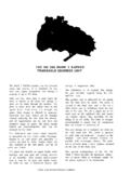
10 Thenet result is that the spiral splined sleeve rotates within the pinion , and the pinion moves endwisealong the haft to engage the ring gear. When the pinion reaches its stop on the sleeve, crankingtakes place, with the initial shock being taken up by the the engine begins to operate, the pinion is driven by the ring gear at a higher speedthan the armature. This causes the pinion to rotate in the same direction as the sleeve but at ahigher speed, and the pinion is driven back out of mesh with the ring gear teeth. For as long as theoperator keeps the motor energized with the engine running, the motor free wheels. The motor startswitch, therefore, should be released immediately after the engine has Starters To The Rest Of Us5A Folo-Thru Bendix drive is illustrated, top, with the pinion and barrel assembly in the crank-ing position and partially cut away to show the internalconstruction.