Transcription of Cross sectional Shape Selection
1 Cross sectional Shape Selection Materials have properties Strength, stiffness, electrical conductivity, etc. A component or structure is a material made into a particular Shape Different shapes are more or less efficient for carrying a particular type of loading An efficient Shape is one that uses the least amount of material for a given strength or stiffness More info: Materials Selection in Mechanical Design , Chapters 11 and 12. ME 474-674 Winter 2008 Slides 9 -1. Mechanical loading and associated components Axial Loading Tension ties or tie rods Compression columns Bending beams Torsion shafts Each type of loading has a different failure mode, and some shapes are more efficient than others for that loading ME 474-674 Winter 2008 Slides 9 -2.
2 Ties or Tie rods Tensile axial loading FL. =. AE. F AE. S= =. L. F. =. A. The stiffness of a tie rod for a given material depends only on the Cross sectional area A and not the Shape The strength of a tie rod depends only on the Cross sectional area A and not the Shape Therefore in tensile loading all shapes of the same Cross - sectional area are equivalent ME 474-674 Winter 2008 Slides 9 -3. Elastic Bending Appendix A-3 gives the deflection of beams as a function of the type of loading. Generally FL3. =. C1 EI. or ML2. =. C1 EI. The stiffness of a beam S is defined as the ratio of load to displacement F. S=.. or M. S=.. Using either definition, S is proportional to EI.
3 E = elastic modulus of the material I = moment of inertia of the Cross section ME 474-674 Winter 2008 Slides 9 -4. Elastic Bending I = Moment of inertia of the Cross section I= dA. 2. y Cross section Table gives the section properties of different shapes For a circular Cross section A = r 2. r 4. A2. IO = =. 4 4 . IfS is the stiffness for another Shape with the same Cross sectional area made of the same material and subject to the same loading, then the Shape factor for elastic bending is defined as S C EI I. Be = = 1 = 4 2. SO C1EI O A. ME 474-674 Winter 2008 Slides 9 -5. Elastic Bending Derive Shape factor for elastic bending of Square Cross -section of side a Hollow tube of radius r and thickness t where r >> t For a square Cross section S sq EI sq 4.
4 Be = = = = SO EI O 12. For a hollow tube S EI I r Be = = = 4 2 =. S O EI O A t ME 474-674 Winter 2008 Slides 9 -6. Elastic Bending - Square Cross -section beam For a square Cross -section of side a A = a2. a 4 A2. I sq = =. 12 12. Compare with a circle with the same area A. 4 . I sq = IO. 12. Shape factor during elastic bending of a square Cross -section relative to a circular Cross section of the same area is: =. e S sq =. I sq =. (A / 12) = 4 = 2. B. SO IO (A / 4 ) 12. 2. Therefore, a square Cross -section is about 5% stiffer than a circular Cross -section ME 474-674 Winter 2008 Slides 9 -7. Elastic Bending Tubular beam For a tubular beam with radius r and wall thickness t where r >> t A = 2 rt I tube = r 3t Shape factor during elastic bending of a tubular beam relative to a circular Cross - section of the same area is: Stube I tube I tube r 3t r =.
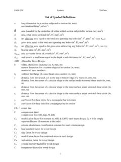
5 E = = 2 = 4 =. B. SO IO (. A / 4 ) (2 rt )2 t Therefore, a thin walled tubular beam with r = 10t is 10 times as stiff as a circular Cross -section beam of the same area Please note that the derivations here assume a circle as the reference Shape . The text book assumes the reference Shape to be a square. ME 474-674 Winter 2008 Slides 9 -8. Elastic Bending The Shape factor Be is dimensionless, it is a pure number that characterizes the Cross - sectional Shape relative to a circular Cross - section I sections with Be = 10. Hollow tubes with Be = 10. Increasing size with constant Shape ME 474-674 Winter 2008 Slides 9 -9. Elastic Bending EduPack Level 3 includes most of the commercially 1e-3.
6 Hot Fin. Steel ( 355 MPa) -( ). available structural shapes Second moment of area (major), I_max (m^4). made from different 1e-4. Pultruded GFRP Vinyl Ester I-section-( ). materials. Phi=100. Using a plot of the moment 1e-5. I. of inertia versus section Be = 4 . area one can compare 1e-6 A2. different structural shapes Hot Rolled Steel ( 355 MPa) Universal Beam-(203x133x25). 1e-7. 1e-8. Extruded Aluminum circular hollow ( 255 MPa)-( ). 1e-9. 1e-10. 1e-11. 1e-4 1e-3 Section area, A (m^2). ME 474-674 Winter 2008 Slides 9 -10. Failure in Bending Failure in bending can be defined as the initiation of plastic deformation in the beam. The stress on the top and bottom surfaces of a symmetric beam is given by Mc M.
7 = =. I Z. where I. Z=. c Where c is the distance of the top or bottom surface from the neutral surface At yield, = f = yield stress ME 474-674 Winter 2008 Slides 9 -11. Failure in Bending For a circular Cross -section . I= r4. 4. c=r Therefore r 3. A3 / 2. ZO = =. 4 4 . ME 474-674 Winter 2008 Slides 9 -12. Failure in Bending Define the Shape factor for failure in bending as Z. =. B. f ZO. Derive For a square of side a 2 Z sq =. B. f = = ZO 3. For a hollow cylinder of radius r and wall thickness t, where r >> t Z r =. B. f = 8. ZO t ME 474-674 Winter 2008 Slides 9 -13. Failure in Bending Square Cross section beam For a square of side a A = a2.
8 A4. I=. 12. I a 3 A (3 / 2 ). Z sq = = =. (a / 2) 6 6. The Shape factor for a square Cross section is =. Z sq =. ( A( 3/ 2). /6. =. ). 2 . = ( ). f (3 / 2 ). /4 . B. ZO A 3. The square Cross section almost 20% stronger than a circular Cross - section ME 474-674 Winter 2008 Slides 9 -14. Failure in Bending Tubular beam For a tubular beam with radius r and wall thickness t where r >> t A = 2 rt I = r 3t I. Z tube = = r 2t r The Shape factor for a tubular beam is Z tube r 2t r 2t r = = (3 / 2 ) =4 =. ( ). f 8. B. ZO A /4 (2 rt )(3 / 2 ) t The tubular beam with r = 10t has a Shape factor of , , the tubular beam is almost 9 times as strong as a circular Cross -section beam ME 474-674 Winter 2008 Slides 9 -15.
9 Elastic Torsion T. During elastic torsion, the angle of twist per unit length is =. JG. Where T is the torque, J is the polar moment of inertia, and G is the shear modulus of the material. A = r 2.. A2. J= r = 4. 2 2 . The stiffness of a solid circular shaft in torsion ST is defined as the ratio of load to angle of twist per unit length T. STO = = J O G.. The Shape factor for a different Cross section is defined as ST GJ J. Te = = = 2. STO GJ O A / 2 ( ). ME 474-674 Winter 2008 Slides 9 -16. Elastic Torsion For a hollow shaft with radius r and wall thickness t where r >> t A = 2 rt J 2 r 3t Shape factor for elastic torsion is 2 r 3t 4 2 r 3t r = 2.
10 E = =. T. (. A / 2 ). 4 2 r 2t 2 t Therefore, a thin walled shaft with r = 10t is 10 times as stiff as a circular Cross - section shaft of the same area ME 474-674 Winter 2008 Slides 9 -17. Failure by plastic deformation during Torsion The shear stress at the surface of a cylindrical shaft subject to a torque T is Tr T T. = = =. J O ( J O / r ) QO. where . JO = r4. 2. and A3 / 2. QO = r = 3. 2 2 . Failure occurs when the stress reaches the shear yield stress, or one-half of the tensile yield stress f T. f = =. 2 QO. The Shape factor for a shaft of a different Cross -section can be defined as Q Q. Tf = = 2 3/ 2. QO A. ME 474-674 Winter 2008 Slides 9 -18.