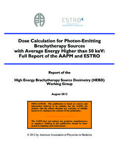
Transcription of CT Image Reconstruction - AAPM
1 CT Image Reconstruction Terry Peters Robarts Research Institute london Canada 1. Standard X-ray Views Standard Radiograph acquires projections of the body, but since structures are overlaid on each other, there is no truly three-dimensional information available to the radiologist 2. Cross-sectional imaging Standard X-rays form projection images Multiple planes superimposed Select slice by moving x-ray source relative to film Simulates focusing of x-rays However, while X-rays cannot be focussed in the same manner as light (as in an optical transmission microscope for example), focussing can be simulated through the relative motion of the x-ray and the recording medium 3.
2 Classical Tomography Xray Tube Motion of X-ray Tube Start position End position Fulcrum plane A A. B B. Object being imaged Film End position Film Start position Motion of Film Classical longitudinal tomography used this principle. By moving the x-ray tube and the film such that the central ray from the tube passes through a single point in the Image -plane (fulcrum plane), information from the fulcrum plane (A A) would be imaged sharply o the film, but data from other planes (B B). would be blurred. Thus although the desired plane was imaged sharply, it was overlaid with extraneous information that often obscured the important detail in the fulcrum plane 4.
3 Transverse Tomography If transverse sections were desired, a different geometry was required. Here the patient and film were rotated while the x-ray tube remained fixed. However the basic principle remained the same: the fulcrum plane was defined by the intersection of the line joining the focus of the x-ray tube, and the the centre of rotation of the film on the pedestal. 5. Transverse Tomography x-ray source Object being imaged Film plane Imaged (fulcrum). plane Direction of rotation This figure illustrates the geometry of the previous slide. Again, while the fulcrum plane is imaged sharply (because its Image rotates at exactly the same rate as the film), structures from planes above and below the fulcrum plane cast shadows that move with respect to the film and therefore the ima ge becomes indistinct as before.
4 6. Transverse Tomogram of Thorax This techniques was known as a Layergraphy, and the Image was known as a layergram. This slide shows a layergram through the thorax, and while a few high contrast structures (ribs), and the lungs are visible, the Image is of limited diagnostic use. 7. Object being imaged Aperture to form (Single spot). laminar beam x-ray source Film plane Image of object Imaged plane Direction of rotation What if we change the geometry of the layergraph so that only a single plane was illuminated? For a single angle of view, a spot in the desired cross-section would project a line over the film.
5 If the object and the film were rotated as before, the lines would intersect on the film to give a blurred representation of the object. 8. Projections of point object Back-projection onto from three directions Reconstruction plane For example, after only three projections, the lines would intersect to yield a star-pattern . 9. Object Image f(r) f(r) *1/r Profile through object Profile through Image And after a full rotation of the film and the object, this pattern would become a diffuse blur. The nature of the blur can readily be shown to be = 1/r. Thus any structure in the cross-section is recorded on the film as a result of a convolution of the original cross-section with the two-dimensional function 1/r.
6 10. Let's get Fourier Transforms out of the way first! .. i 2 ux f ( x) = F (u ) e du . forward Fourier Transform . F (u ) = .. f ( x)e i 2 ux dx inverse Fourier Transform Since the Fourier Transform plays a major role in the understanding of CT. Reconstruction , we introduce it here to define the appropriate terms. 11. Reconstruction Image is object blurred by 1/r 2D FT of 1/r is 1/ . Why not de-blur Image ? 2D FT of Image Multiply FT by | |. Invert FT. Voila! Back to the blurred layergram! If the Image is blurred with a function whose FT is well behaved, we should be able to construct a de-blurring function.
7 It turns out that the 2-D FT of 1/r is 1/ . Since the inverse of 1/ is | |, then we should be able to compute the 2D FT of the blurred Image , multiply the FT of the result Image by | | , and then calculate the inverse FT. 12. There's more scan than one way to skin a CAT. The previous approach is certainly one approach, but not necessarily the most efficient. There are in fact a number of different ways to view the Reconstruction process. 13. Central Slice Theorem Pivotal to understanding of CT. Reconstruction Relates 2D FT of Image to 1D FT of its projection 2D FT is k-space of MRI. One of the most fundamental concepts in CT Image Reconstruction if the Central-slice theorem.
8 This theorem states that the 1-D FT of the projection of an object is the same as the values of the 2-D FT of the object along a line drawn through the center of the 2-D FT plane. Note that the 2-D Fourier plane is the same as K-space in MR Reconstruction . 14. Central Slice Theorem 2D FT.. Projection at angle 1D FT of Projection at angle . The 1-D projection of the object, measured at angle , is the same as the profile through the 2D FT of the object, at the same angle. Note that the projection is actually proportional to exp (- u(x)xdx) rather than the true projection u(x)xdx, but the latter value can be obtained by taking the log of the measured value.
9 15. Horizontal Projection 2-D Inverse FT. 1-D Fourier Transform Vertical Projection Interpolate in Fourier Transform 1-D Fourier Transform 2-D Fourier Transform If all of the projections of the object are transformed like this, and interpolated into a 2-D Fourier plane, we can reconstruct the full 2-D FT of the object. The object is then reconstructed using a 2-D inverse Fourier Transform. 16. Filtered Back-projection Direct back-projection results in blurred Image Could filter (de-convolve) resulting 2-D. Image Linear systems theory suggests order of operations unimportant Filter projection profiles prior to back projection Yet another alternative, (and the one that is almost universally employed).
10 Employs the concept of de-blurring, but filters the projections prior to back- projection. Since the system is linear, the order in which these operations are employed is immaterial. 17. Convolution Filter In Fourier Space, filter has the form | |. Maximum frequency must be truncated at '. Filtering may occur in Fourier or Spatial domain ' ' . 0. Frequency response of filter Sampled convolution filter Since the Fourier form of the filter was already shown to be | |, the spatial form is the inverse FT of this function. The precise nature depends on the nature of the roll-off that is applied in Fourier space, but the net result is a spatial domain function that has a positive delta-function flanked by negative tails.