Transcription of Current Ratings Table 4D5 70°C thermoplastic …
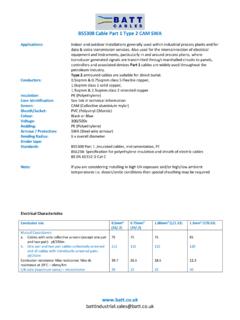
1 Current Ratings Table 4D5 70 C thermoplastic insulated and sheathed flat cable with protective conductor ( copper conductors) Current Carrying Capacity (amperes) and Voltage Drop (per ampere per metre) Ambient temperature: 30 C, conductor operating temperature: 70 C conductor cross-sectional area Reference method 100 (above a plasterboard ceiling covered by thermal insulation not exceeding 100mm in thickness) Reference method 101 (above a plasterboard ceiling covered by thermal insulation exceeding 100mm in thickness) Reference method 102 (in a stud wall with thermal insulation with cable touching the inner wall surface) Reference method 103 (in a stud wall with thermal insulation with cable not touching the inner wall surface Reference method C* (clipped direct) Reference method A* (enclosed in conduit in an insulated wall) Voltage drop (per ampere per metre) 1 2 3 4 5 6 7 8 (mm ) (A) (A) (A) (A) (A) (A) (mV/A/m))
2 1 13 13 8 16 44 16 13 16 10 20 29 21 17 21 27 20 18 4 27 22 27 37 26 11 6 34 27 35 47 32 10 45 36 47 32 64 44 16 57 46 63 85 57 A* For full installation method refer to Table 4A2 Installation method 2 but for flat twin and earth cable C* For full installation method refer to Table 4A2 Installation method 20 but for flat twin and earth cable 100 For full installation method refer to Table 4A2 Installation method 100 101 For full installation method refer to Table 4A2 Installation method 101 102 For full installation method refer to Table 4A2 Installation method 102 103 For full installation method refer to Table 4A2 Installation method 103 Wherever practicable a cable is to be fixed in a position such that it will not be covered with thermal insulation Regulation , BS5803-5; Appendix C: Avoidance of overheating of electric cables Building Regulations Approved document B and Thermal insulation; avoiding risks, BT 262, BRE, 2001 All tables are reproduced by kind permission of The Institution of Engineering & Technology from IEE Regs, 17th Ediiton.
3 However, it should be noted that in order to apply these tables correctly, reference is required to appendix 4 of the 17th edition of the wiring regulations which may be obtained from: Institution of Engineering & Technology, Michael Faraday House, Six Hills Way, Stevenage, Hertfordshire, England, SG1 2AY