Transcription of CVS Type 67AFR Filter Regulator
1 1 Product Manual CVS Type 67 AFR Filter Regulator Introduction This CVS Controls product manual includes instructions for the installation, adjustment, maintenance and parts ordering of the CVS Type 67 AFR Filter Regulator . All CVS Controls equipment should be installed, operated and maintained by qualified personnel. If you have any questions regarding this equipment, contact your CVS Controls representative. Ensure that the label of the control spring range is updated to reflect any changes in field equipment, materials, service conditions or pressure settings. If any venting occurs or a leak develops in the pressure system this indicates that service is required.
2 Failure to remove the Regulator from service for immediate maintenance may cause a hazardous situation. These regulators are often shipped installed on other equipment. Information on that equipment will be contained in separate manuals. Description The CVS Type 67 AFR Filter Regulator is a self-operated unit which provides continuous reduced pressures in a variety of applications and service conditions. Common use is as supply pressure regulators for pneumatic instruments. A cellulose Filter is used with the CVS Type 67 AFR Filter Regulator and will remove particles greater than inch ( mm) in diameter. In addition, these regulators contain integral low-capacity relief valves.
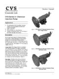
3 In this type of construction the valve stem Figure 1: CVS Type 67 AFR Regulator sits against an orifice in the diaphragm assembly. When downstream pressure increases above the set point, the diaphragm assembly moves off the valve stem and excess pressure is vented through a port hole tapped in the spring case. Installation Warning Do not install any pressure equipment where service conditions exceed the manufacturer s specifications. Over pressuring of Regulator may result in leakage, equipment damage or injury. Excessive pressure can cause the pressure-containing parts to burst, or accumulated gas to explode. The CVS Type 67 AFR Filter Regulator cannot be used with hazardous gas unless vented to a safe area.
4 CVS Controls Ltd Product Manual: CVS Type 67 AFR Filter Regulator 2 SpecificationsBody Size and End Connection Style 1/4- inch NPT screwed Maximum Allowable Inlet Pressure 250 psig (17 bar) Outlet Pressure Ranges 3 to 100 psig ( to bar) available in four ranges. Refer to Parts List Key 5 Maximum Emergency Outlet Pressure 50 psig ( bar) over outlet pressure setting, or 110 psig ( bar), whichever is greater Pressure Registration Internal Standard Elastomers -29 to 66 C (-20 to 150 F) Material Temperature Capabilities High Temperature Elastomers -18 to 188 C (0 to 350 F) Installation continued As with many regulators , the outlet pressure rating on the CVS Type 67 AFR Filter Regulator is lower than the inlet pressure rating.
5 If it is possible for the actual inlet pressure to exceed the Regulator outlet pressure setting or the pressure ratings of any downstream equipment, downstream over-pressure protection is required. The low-capacity internal relief feature of the CVS 67 AFR provides some limited downstream overpressure protection but should not be relied upon to completely safeguard against overpressure. Debris in the service line or other external conditions may cause damage to the Regulator even while it is operating within normal set pressure ratings. Regular inspection should be scheduled in addition to inspections after any overpressure condition.
6 Note If the Regulator has been installed on another unit prior to shipping, perform the installation according to the instruction manual for that unit. For CVS Type 67 AFR regulators shipped separately, check the Regulator , tubing and piping for damage. Remove any foreign material. Install the Regulator ensuring that flow is from the IN to the OUT as marked on the Regulator body. Refer to Figure 2 for cutout dimensions for a panel mounted Regulator . To use the unit in Regulator shutdown, properly vent the Regulator inlet and outlet pressures by installing upstream and downstream vent valves or providing some alternate means of properly venting the inlet and outlet pressures.
7 For optimum Filter drainage, position the drain valve (Key 11) at the lowest possible point on the Filter cap (Key 9). Prevent plugging of the spring case vent and keep the spring case from collecting moisture, corrosive chemicals or other materials by orienting the vent to the lowest possible point on the spring case. To change the Filter /drain orientation, rotate the Filter cap with regards to the Regulator body. Change the spring case/vent orientation by rotating the spring case in relation to the Regulator body. Any CVS type 67 AFR Filter Regulator with a tapped spring case can be vented remotely by installing tubing or piping into the - inch NPT vent tapping.
8 Install a screened vent cap in the end of the tubing or piping to prevent clogging. If using piping, apply pipe compound to threads then proceed with making the connections. First install the piping or tubing into the - inch NPT inlet connection. Unless the outlet connection has been made at the factory to another unit, install the piping or tubing to the outlet connection. Warning Never adjust the control spring to produce pressure beyond its highest outlet pressure range. Over pressuring the spring can cause bursting of pressure containing parts, or explosion of accumulated gas. If the range of the control spring does not reach the desired outlet pressure install a spring with the proper range according to the maintenance section.
9 CVS Controls Ltd Product Manual: CVS Type 67 AFR Filter Regulator 3 Installation continued CVS Controls sets each Regulator for the pressure setting specified at the time of ordering. If no setting was indicated, the outlet pressure will be set at the midrange of the control spring. Startup Refer to Figure 2 for Key Numbers. After completion of installation and adjustment of downstream equipment, introduce pressure to the unit by slowly opening the upstream and downstream shutoff valves. During any startup or adjustment, monitor the adjustment using pressure gauges. Outlet pressure of the Regulator can be monitored using a gauge installed at a downstream position, including the supply pressure gauges of a pneumatic instrument where the Regulator is providing reduced pressure.
10 If the Regulator has a tapped side outlet a gauge (Key 20, not shown) may be installed for monitoring. If the Regulator has no gauge but the side outlet has been tapped and plugged, the side plug may be removed and a temporary gauge installed. During the adjustment procedure monitor the outlet pressure with a gauge, if outlet pressure is necessary; adjust the standard CVS Type 67 AFR Regulator by loosening the locknut (Key 2) and turning the adjusting screw or handwheel (Key 1). Clockwise adjustment will increase the outlet pressure setting, and counter-clockwise adjustment will decrease the outlet pressure setting. On some regulators , a closing cap (Not shown) will have to be removed prior to adjustment and replaced afterward.