Transcription of D.C. TRACK CIRCUIT - Indian Railways
1 CAMTECH/S/2004/ TRACK CIRCUIT Ver TRACK CIRCUIT1. Introduction TRACK CIRCUIT is a low powered electrical circuitin which running rails are used as a part. Withthe help of TRACK CIRCUIT , one can easily identifywhether the particular section is clear oroccupied by a train/vehicles or TRACK CIRCUIT isin failed advantages of DC TRACK CIRCUIT are : It is very simple to maintain. It is highly reliable for effective and saferunning of DC TRACK CIRCUIT has mainly two ends feedend and relay end as shown in fig. no. TRACK CIRCUIT gives two indications. Yellow/White/No light indication -When TRACK CIRCUIT portion is clear line is unoccupied. Red indication - When TRACK circuitportion is occupied by a vehicle or trackcircuit is in fail TRACK CIRCUIT Ver 20042.
2 Requirements Permanent Way Requirements Glued joints or insulation joints of approvedtype are to be provided for definingboundary of TRACK CIRCUIT . In all future worksof TRACK circuiting, glued insulated joints isto be preferably been provided. Insulated joints wherever provided is to bemaintained as square joints. Wherestaggering can not be avoided the distancebetween staggered joints shall not exceed theminimum wheel based of the vehicles. Rail ends of insulated joints shall be squareand true. All rough edges and burrs shall beremoved from bolts holes. Battered endsshall be put right and the gap between therails is to be equal to the thickness of the endpost. Fish bolts at the joints must be kept tight andthe sleepers well packed in the vicinity ofthe joints.
3 Proper drainage should be ensured so as toavoid flooding of tracks during rains,particularly in the yards where watering ofcoaches is done and in the water columnsand ash pits. It would be desirable to providewashable concrete aprons on platform linesat originating stations, in TRACK TRACK CIRCUIT Ver 2004 Ballast shall be kept clean throughout thetrack circuited section should be taken dosee that the ballast is kept clear off the railsand rail fastenings. The clearance from thefoot of the rail should not less than 50 screened ballast right up to theformation level shall be provided. Rail ends shall be kept free from brake-dust,sand, rust, other foreign materials etc. allrough edges and burrs at rail ends must beremoved.
4 To avoid crushing of end posts of insulatedrail joints due to creep at least one rail lengthin either side of insulated joint should beprovided with anti creep devices. Rail screws should preferably be used inplace of dog spikes at insulated joints. Wooden sleepers concrete sleepers or anyother approved type insulated sleepers shallbe provided for TRACK circuiting. Concretesleepers where used shall have a minimumresistance of 500 ohms between insert-to-insert. Where short welded rail panels are used,SWR shall not but against insulated rails lengths of 13 meters/12 metersshall be interposed to isolate short weldedrail from insulated joint. This standardlength of rails shall be anchored effectivelyto arrest movement in either direction.
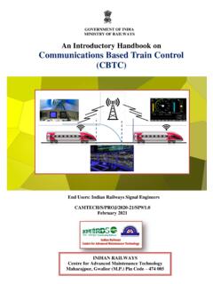
5 In case of turnouts and crossings, insulatedstretchers, insulated gauge ties plates andCAMTECH/S/2004/ TRACK CIRCUIT Ver 2004insulated crossings plates shall be providedas per approved drawings. GEN liners shall be provided in the TRACK -circuited area using concrete Types of TRACK circuits A closed type TRACK CIRCUIT shall be provided toprove the clearance of rail TRACK . Double rail TRACK CIRCUIT Double rail TRACK CIRCUIT is to be provided onnon RE areas, as for as practicable. In double rail TRACK CIRCUIT both the runningrails are insulated from adjoining sections byinsertion of block + -InsulationjointsDouble Rail TRACK CIRCUIT (Figure 1)CAMTECH/S/2004/ TRACK CIRCUIT Ver 2004 Single rail TRACK CIRCUIT In RE area, generally single rail trackcircuit is used where one of the rails isreserved for the traction return rail is referred to as the un-insulatedrails.
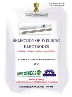
6 Any connection from the OHE mast orother structure shall be made only to theun-insulated rails. Similarly, connections for the returncurrent at feeding points as well as frombooster transformers and returnconductors shall be made only to the un-insulated rail. Other rail carries positive polarity of DCrack CIRCUIT . This positive polarity rail isinsulated from either TRACK CIRCUIT Ver 2004 TRInsulationJoint6 Amp Fuse Choke + -Single Rail TRACK CIRCUIT (Figure 2) As far as practicable, the rail adjacent tothe mast shall be utilised as theinsulated rail. However, this may notalways be possible, particularly in yardswhere there are a large number of pointsand crossings or where the mastsCAMTECH/S/2004/ TRACK CIRCUIT Ver 2004are not always on the same side or wheretrack circuits are staggered.
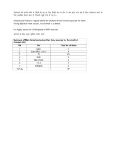
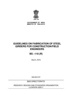
7 In single rail TRACK circuits, in the eventof a break in the un-insulated rails, veryheavy current will flow through thetrack relay as well as the equipment atthe feed point. To avoid this the un-insulated rails of the adjacent tracks shallbe cross-bonded at intervals of not morethen 100 mts. In case the TRACK CIRCUIT isless then 100 mts. The cross bondingshall be provided on the un-insulated railat either end of the TRACK TRACK CIRCUIT Ver 2004 TRInsulationBreakUn insulatedJoint railTraction6 Amp FuseReturn current Choke + -Single Rail TRACK CIRCUIT with Breakage onUn insulated Rail(Figure-3) To avoid this the un-insulated rails of theadjacent tracks shall be cross-bonded atintervals of not more than 100 mts. Incase the TRACK CIRCUIT is less than 100 cross bonding shall be provided onthe un-insulated rails at either end of thetrack TRACK CIRCUIT Ver 2004 In case of adjacent TRACK circuits, thereturn rail shall be staggered as shown infig.
8 TRACK CIRCUIT (Figure-4)4. Length of TRACK length The length of the TRACK CIRCUIT shall not be lessthen the maximum wheel base of any vehicle,except in marshalling yards. TRACK circuits shall cover at least two raillengths ( meters) length As per SEM pera the maximum lengthof TRACK CIRCUIT under different TRACK parametersare given in the table areaSleeperSectionyardBlock Type oftrack relayto be used2T1 TTraction BondCAMTECH/S/2004/ TRACK CIRCUIT Ver 2004sectionresistance inOhmsperKmtrackcircuit Non type 4 or9 Ohms orshelf typerelayNon 9 OhmsAC immuneor shelf type9 Ohms incunjuct-ionwith QSPA1with B typechoke atrelay end.(Table - 1)5. Description & working (Closed Type)CAMTECH/S/2004/ TRACK CIRCUIT Ver 2004 TRACK CIRCUIT is designed to know whetherthe portion of rail ( TRACK circuited) is clearor occupied by a train.
9 A TRACK CIRCUIT has two ends feedend and relay end. Both the ends areinsulated by a Nylon joint or glued joint. Feed end is connected to power source andrelay end is connected to TRACK relay. Trackrelay will be in de-energised position underfollowing conditions: A vehicle occupies any part of thetrack CIRCUIT or It is short-circuited by any means. Otherwise TRACK relay will be inenergised position. Since it is a vital safety CIRCUIT , henceinstallation is to be made according to theapproved interlocking Specification of equipment required for DCtrack CIRCUIT in RE TRACK CIRCUIT Ver feedchargerIRS-89/932 B typechokeIRS-65/833 F typeresistanceRE/S&T/ALD/SPEN/1284 ACImmunizedtrack relayBRS 939 ABRS 966 A/BS 1659 WITH 40 AHIS-1651 (Table - 2) parts Non- RE Area Following are the main parts of a DC trackcircuit.
10 Relay Relay must conform to British StandardSpecification , unless otherwisespecially permitted. The approved typeissue relays are: Shelf type Q series typeCAMTECH/S/2004/ TRACK CIRCUIT Ver 2004 The resistance of the TRACK relay shouldbe 9 ohm for the length of TRACK circuitsup to and less than 100 Mtrs. The resistance of the TRACK relay shouldbe Ohm for a length of TRACK circuitabove 100 Mtrs. if the TRACK is laid onwooden sleepers and 9 Ohm if laid onconcrete sleepers. TRACK Feed Power supply given to DC TRACK CIRCUIT at feedend: Approved type of primary cells or lead acidsecondary cells shall be used. Where primary cells are used, two batteriesin parallel shall be used to increasereliability. Where secondary cell(s) is/are used, theyshall be used with battery charger/solarpanels of adequate capacity.