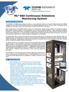
Transcription of D-R 290 Dust and Opacity Monitor Installation and operation
1 11/2002 Durag, Inc 1355 Mendota Heights Road Suite. 200 Mendota Heights, MN 55120 Phone: 651-451-1710 Fax 651-457-7684 Website: D-R 290 Dust and Opacity Monitor Installation and operation D-R 290 2 Table of Contents Figures .. 3 1. Applications .. 4 2. Basic Features .. 4 3. Operating Overview .. 5 Opacity Calculation at the Stack exit .. 7 Extinction Measurement Principle .. 8 Measurement .. 12 Internal Reference .. 12 Internal Zero Check .. 13 Upscale Calibration Check .. 13 System Components .. 14 Configuration options for stack and control room 16 4. Selection of the Measuring Location .. 17 5. Installation .. 17 Flange Installation .. 17 Blower Panel and Weather Hood Installation .. 18 Weather Hood and Blower Panel Electrical Installation .. 20 D-R 290 AZG Stack-Mounted Display Module .. 21 Electrical Installation , D-R 290 AZG Stack-Mounted Display Module.
2 22 Transceiver and Reflector Installation .. 23 Transceiver and reflector alignment and focus .. 24 Transceiver and reflector electrical Installation .. 25 D-R 290 AW Evaluation Unit Installation .. 25 D-R 290 AW Electrical Connection when used with D-R 290 AZ .. 27 D-R 290 AW Stand Alone Electrical Connection (No D-R 290 AZ) .. 29 6. operation .. 30 operation of the D-R 290 AW evaluation unit .. 30 Parameters .. 30 Key functions .. 34 Saving / Data entry .. 34 Liquid Crystal Display (LCD) .. 36 Switch settings and operation with or without the D-R 290 AZ .. 37 operation of the D-R 290 AZ Stack Display Unit .. 37 Reflector operation .. 38 Transceiver operation .. 38 Maintenance .. 38 Transceiver circuit board .. 39 Transceiver Switch Functions .. 39 Clear Path Procedure .. 41 Manual internal zero point (Window Check) .. 44 External Zero Point Calibration.
3 44 7. Error Messages .. 45 8. Purge air system .. 46 9. D-SK 290 Fail-safe Shutters .. 46 Function .. 47 Installation .. 48 Electrical Connection D-SK 50 Automatic check of shutter operation .. 51 Shutter operation .. 52 10. Technical Specifications .. 53 Technical Specifications: D-R 290 .. 53 Technical Specifications for the Purge Air Blower .. 53 Technical Specifications for the D-SK AE Electronics .. 54 Technical Specifications for the D-SK 290 MA Mechanics .. 54 D-R 290 3 Figures (Fig. ) Relationship between Extinction, Transmission and Opacity .. 6 (Fig. ) Reference locations for determining Opacity .. 7 (Fig. ) Optics diagram D-R 290 .. 11 ( 4) System components .. 14 (Fig. ) D-R 280-10E Installation flange for D-R 290 Opacity Monitor .. 18 (Fig. ) Weather hood dimensions .. 19 (Fig. ) Transceiver side interconnect wiring, typical .. 20 (Fig. ) Reflector side interconnect wiring, typical.
4 20 (Fig. ) D-R 290 AG wall mount housing dimensions .. 21 (Table ) D-R 290 AZ stack display I/O .. 22 (Fig. ) Mounting Monitor on the Installation flange .. 23 (Fig. ) D-R 290 BT dimensional diagram .. 26 (Fig. ) D-R 290 AW19 dimensional diagram .. 26 (Fig. ) D-R 290 BT terminal connectors .. 27 (Table ) D-R 290 AW mounted in D-R 290 BT housing, terminal connections .. 28 (Table ) D-R 290 AW mounted in D-R 290 AG housing, terminal connections (No D-R 290 AZ) .. 29 (Table ) How set-up mode changes I/O .. 31 (Fig. ) D-R 290 AW Key Functions .. 34 (Fig. ) D-R 290 AW operating 35 (Table ) D-R 290 AW and AZ processor board switch functions .. 37 (Fig. ) Transceiver switch functions .. 39 (Table ) Error messages .. 45 ( ) Dimensions (in mm) of shutter (D-SK 280 MA) .. 47 (Fig. ) Dimensions (in mm) of control electronics D-SK AE .. 48 (Fig. ) Air Flow Sensor .. 49 (Fig. ) D-SK 290 Mounting .. 49 (Fig. ) Electrical Connection for the D-SK AE.
5 50 (Fig. ) Electrical connection between the D-R 290 AZ and the fail-safe shutter .. 51 Valid for PROM version and higher D-R 290 4 1. Applications The Durag D-R 290 Opacity Monitor can be used for continuous emissions monitoring in smokestacks, exhaust ducts, and other similar applications. This Monitor has been designed to comply with the new Performance Specification 1 found in 40 CFR part 60, Appendix B and the ASTM D6216-98 standard. This type of Opacity Monitor is necessary for the legal and economically sound operation of power plants, heating plants and other industrial large boiler facilities. These systems are also critical for use in the chemical and cement industries where careful monitoring of the industrial processes is a criterion for problem-free operation . Durag Opacity monitors have functioned successfully for years in applications where dust emissions could have potentially damaging environmental pollution effects.
6 The data they collect is incorruptible, precisely reproducible, unaffected by seasonal changes or weather conditions, and functions easily in either automatic or manual operation . These systems have been used for applications in refineries and other facilities of the petrochemical industry, in waste-burning facilities and many others. 2. Basic Features continuous , in situ measurement directly in the exhaust stream without disruption or dust sampling. The white light semi-conductor light source has a long life. The wide spectrum of the Super-Wide Band Diode (SWBD) optimizes system accuracy because the measurements are more stable than those made with conventional LEDs. Modern microprocessor technology and software allow digital information processing. LCD shows measurements as Opacity or extinction. Automatic calibration cycle corrects values for window contamination. Purge air system protects the reflector and heated exit window reduce maintenance.
7 Control panel with digital display makes Installation and operation simple. Hermetically sealed optics and electronics prevent dust or smoke from damaging internal system components. Two analog outputs with selectable measuring ranges on each system. Optional Fail-safe shutter system protects the transceiver and reflector. Protective weather hoods for transceivers, reflectors, and purge air systems. Stack mounted display for single person filter audits. D-R 290 5 3. Operating Overview The transceiver emits a beam of light which passes through the stack or duct and strikes a reflector. The light beam is reflected back and the amount of light returned is measured by the transceiver. Dust particles in the stack will absorb and scatter the transmitted beam of light so the returned light will be less than the transmitted light. The ratio of the returned light to the transmitted light is call the transmission. One minus the transmission is referred to as Opacity .
8 For dust concentration measurements optical density (also called extinction) is historically used because the dust concentration is linear to the optical density value. The log of 1 divided by the transmission give the optical density. The measured transmission value is sent via RS 422 to the stack display (D-R 290 AZ). From this local display the measured value can be read and maintenance actions can be initiated. Also purge air alarms are wired into this stack display. From here the measured value and any purge air failure is sent via RS422 to the evaluation unit (D-R 290 AW). At the evaluation unit the measured value is displayed and system parameters can be viewed or changed. This remote display also contains the status inputs, relay outputs and the 2 independent current outputs. One current output could be set to read Opacity and the other to read the dust concentration. If dust concentration is required, normally a stack test is needed to calibrate the extinction reading to a concentration (determine the extinction coefficient).
9 Purge air blowers are used to keep the optics clean. Weather hoods are used to protect the blowers and the Opacity system. Fail-safe shutters can be installed to protect the optics if a purge air blower should fail or loose power and may also protect service personnel on over pressure stacks. These shutters are exercised during the daily calibration to insure they are in working order when needed and to prevent them from sticking in the open Durag D-R 290 Opacity Monitor is designed to utilize the principles of light transmission. The transceiver and reflector are mounted opposite one another. Using the auto collimation principle, the light beam traverses the distance to be measured twice. This significantly increases the sensitivity of the measurements made by the system. The light beam loses intensity proportionally to the particle concentration of the air. The light beam has a significantly larger diameter than the reflector surface.
10 This makes alignment easier and reduces measurement errors caused by possible heat-induced shifts in the transceiver or reflector mounting flanges. D-R 290 6 Transmission Measuring Principle If a light shines through a smoke stack or dust exhaust duct, this light beam will become weaker as the dust density increases. Transmission is the ratio of the intensity of the light received (I) compared to the intensity of the light transmitted (I0). The relationship between the irradiated light and the received light is given as a percent value, as shown in equation 2. Subtracting the transmission measurement from one gives the Opacity value. Opacity is the default measurement mode of the D-R 290, since this results in an increasingly strong signal at the detector as the dust density diminishes. C (Fig. ) Relationship between Extinction, Transmission and Opacity D-R 290 7 Because the D-R 290 operates on the auto collimation principle, the light beam being measured crosses the measurement region twice.