Transcription of D101634X012 January 2021 Fisher HP and HPA Control Valves
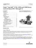
1 Instruction Manual HP and HPA Valves D101634X012 July 2017. Fisher HP and HPA Control Valves Contents Figure 1. HP Valve with 667 Actuator and Introduction .. 1 FIELDVUE dvc6200 digital Valve controller Scope of Manual .. 1. Description .. 2. Specifications .. 3. Educational Services .. 3. Installation .. 3. Maintenance .. 6. Packing Lubrication .. 8. Packing Maintenance .. 8. Adding Packing Rings .. 8. Replacing Packing .. 9. Trim Removal .. 14. Valve Plug Maintenance .. 15. Lapping Seats .. 17. Trim Replacement .. 20. Retrofit: Installing C seal Trim .. 24. Replacement of Installed C seal Trim .. 26. Trim Removal (C seal Constructions) .. 26. Lapping Metal Seats (C seal Constructions).
2 27. Remachining Metal Seats (C seal Constructions) .. 27. Trim Replacement (C seal Constructions) .. 28. Parts Ordering .. 30. Parts Kits .. 30 X0183-1. Parts List .. 36. Introduction Scope of Manual This instruction manual includes installation, maintenance, and parts information for NPS 1 through 6 HP Valves with CL900 and CL1500 ratings; NPS 1 through 2 HP with CL2500 ratings; NPS 1 through 8 HPA Valves with CL900 and CL1500 ratings; and NPS 1 through 2 HPA Valves with CL2500 ratings. Refer to separate manuals for instructions covering the actuator, positioner, and accessories. Do not install, operate, or maintain HP series Valves without being fully trained and qualified in valve, actuator, and accessory installation, operation, and maintenance.
3 To avoid personal injury or property damage, it is important to carefully read, understand, and follow all the contents of this manual, including all safety cautions and warnings. If you have any questions about these instructions , contact your Emerson sales office or Local Business Partner before proceeding. Unless otherwise noted, all NACE references are to NACE MR0175 2002 and MR0103. HP and HPA Valves Instruction Manual July 2017 D101634X012 . Table 1. Specifications End Connection Styles and Ratings(1,2,3,4) Standard Cage with Micro Flat Valve Plug: (HPAS. only): J Linear Flanged: Consistent with CL900, CL1500, and CL2500. per ASME Cavitrol III, Whisper Trim III, or WhisperFlo.
4 Cage: J Linear Socket Welding: Consistent with CL900, CL1500, and CL2500 per ASME Special cages: Special characterized flow cages are available. Consult your local Emerson sales office or Buttwelding: Consistent with CL900, CL1500, and Local Business Partner. CL2500 per ASME Also see table 2 Flow Direction Standard Cage Shutoff Classifications J HPD and HPAD: Normally flow down See table 3 J HPS and HPAS: Normally flow up(5). J HPAS Micro Flat: Flow down C seal trim: High temperature, Class V. J HPT and HPAT: Normally flow down See table 4. J HPS and HPAS Micro Form: Flow up only TSO (Tight Shutoff) trim: See tables 5 and 6 Cavitrol III Cage: Flow down Whisper Trim III or WhisperFlo Cage: Flow up Flow Characteristic Standard Cage: J Equal percentage, J Modified Approximate Weights (valve body and bonnet equal percentage, or J Linear assemblies).
5 Standard Cage with Micro Form Valve Plug: (HPS and See table 2. HPAS only): J Equal percentage or J Modified equal percentage Additional Specifications Standard Cage with Micro Flute Valve Plug: (HPS and For specifications such as materials, valve plug HPAS only): J Equal percentage or J Modified equal travels, and port, yoke boss, and stem diameters, see percentage the Parts List section 1. EN (or other) ratings and end connections can usually be supplied; consult your Emerson sales office. 2. CL900 and CL1500 globe Valves are identical for NPS 1 and 2 Valves . CL900 and CL1500 globe Valves for NPS 3, 4, and 6 Valves , however, are not identical. 3. The centerline to face dimension for CL2500 NPS 1 and 2 HPA Valves does not conform to ANSI/ISA 4.
6 The pressure or temperature limits in this manual and any applicable standard limitations should not be exceeded. 5. HPS and HPAS Valves may be used flow down for on off service only or where further limited by trim design. HPAS Valves may be used flow down for erosive service. Description HP Series high pressure globe and angle Valves (figure 1) have metal seats, cage guiding, quick change trim, and push down to close valve plug action. HPD, HPAD, HPT, and HPAT Valves use balanced valve plugs. HPS and HPAS. Valves use an unbalanced valve plug. To provide a seal between the cage and a balanced valve plug, the HPD and HPAD. valve plugs use piston rings; the HPT and HPAT valve plugs use a pressure assisted seal ring.
7 A Whisper Trim or WhisperFlo cage can be used with an HPD, HPAD, HPS, HPAS, HPT, or HPAT valve plug. A Cavitrol III cage can be used with an HPS, HPAS, HPT, or HPAT valve plug. C seal trim is available for HPD Valves , CL900 and CL1500, in sizes NPS 3, 4, and 6; and for HPAD Valves , CL900 and CL1500 in sizes NPS 4, 6, and 8. With C seal trim, a balanced valve can achieve high temperature, Class V shutoff. Because the C seal plug seal is formed from metal (N07718 nickel alloy) rather than an elastomer, a valve equipped with the C seal trim can be applied in processes with a fluid temperature of up to 593_C (1100_F), provided other material limits are not exceeded.
8 2. Instruction Manual HP and HPA Valves D101634X012 July 2017. Specifications Specifications for the HP Series Valves are shown in table 1. Table 2. Approximate Weights (Valve and Bonnet Assemblies). VALVE SIZE, KILOGRAMS POUNDS. PRESSURE RATING. NPS Flg SWE & BWE Flg SWE & BWE. Globe Valves CL900 & CL1500 42 38 93 85. 1. CL2500 45 34 100 76. 1 1/2 x 1 CL2500 34 76. CL900 & CL1500 72 52 158 115. 2. CL2500 104 74 229 164. CL900 125 276 . 3. CL1500 129 97 284 213. CL900 230 507 . 4. CL1500 249 201 548 444. CL900 511 1127 . 6. CL1500 557 455 1228 1003. Angle Valves CL900 & CL1500 40 36 88 80. 1. CL2500 72(1) 160(1). CL900 & CL1500 69 50 153 110. 2. CL2500 109(1) 240(1).
9 3 CL1500 123 78 278 173. 4 CL1500 181 117 399 258. 6 CL1500 357 202 788 445. 8 CL1500 648 405 1428 893. 1. Only SWE is available for CL2500. Educational Services For information on available courses for Fisher HP and HPA Valves , as well as a variety of other products, contact: Emerson Automation Solutions Educational Services - Registration Phone: 1-641-754-3771 or 1-800-338-8158. E-mail: Installation WARNING. Always wear protective gloves, clothing, and eyewear when performing any installation operations to avoid personal injury. Personal injury or equipment damage caused by sudden release of pressure may result if the valve assembly is installed where service conditions could exceed the limits given in table 1 or on the appropriate nameplates.
10 To avoid such injury or 3. HP and HPA Valves Instruction Manual July 2017 D101634X012 . damage, provide a relief valve for over pressure protection as required by government or accepted industry codes and good engineering practices. Check with your process or safety engineer for any additional measures that must be taken to protect against process media. If installing into an existing application, also refer to the WARNING at the beginning of the Maintenance section in this instruction manual. WARNING. Some bonnet flanges have a tapped hole that was used to handle the bonnet during manufacture. Do not use this tapped hole to lift the valve assembly or personal injury may result.