Transcription of DATA SHEET - シチズン電子株式会社
1 data SHEET . CITILED COB Series High-CRI Type On CLU026-1204C1. Introduction P 2. Performance Characteristics P 3. Mechanical Dimensions P 5. Characteristic Curves P 6. Reliability P 9. Packing Specification P 10. Precaution P 11. 1. 04/15. Product Nomenclature CLU026 - 12 04 C1 - 27 3 H5 G3. [1] [2] [3] [4] [5]. [1] Product shape CLU026. [2] Die count in series 12. [3] Die count in parallel 04. [4] Nominal CCT 2700K. [5] CRI (Ra) 1. Introduction 1-1. Product Description CITIZEN ELECTRONICS is the first COB manufacture. Our advanced knowledge and packaging technology for many years has excellent reliability and high quality of our products.
2 CITILED COB Series covers a wide range of luminous flux from a 10W incandescent bulb to a 300W mercury lamp in general lighting sources. The element arrangement of LED. package is capable of utilizing light more effectively and higher performance. The new version of CITILED COB series increase the performance significantly from previous version. New version creates more options to match luminaire's products design (ex. High performance , Cost effective , Small Light Emitting Surface(LES), Increased allowable max. If). Emitted light density of the LED package is improved higher for suitable use of light-condensing products.
3 The outline and LES size is the same as for previous version. Thus existing parts of 3rd parties are compatible in mechanical characteristics. All of specs are at hot binning (Tj=85 ). 1-2. Features Mechanical Dimensions : (mm). Package Structure : Aluminum Base Chip on Board Reference Assembly : M3 screw, Connector CRI (Ra) : 90 Min. Nominal CCT : 2,700K, 3,000K, 3,500K, 4000K. Chromaticity Range : 3-step MacAdam Ellipse, the center refers to ANSI :2011. Thermal Resistance : Maximum drive current : 920mA. RoHS compliant Better die arrangement for optics Wide range of luminous flux and high efficacy Improved lumen density compared with previous version 2.
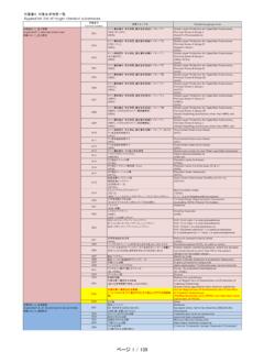
4 04/15. 2. Performance Characteristics 2-1. Electro Optical Characteristics Electro Optical Characteristics ( Tj=85C ). Luminous flux Thermal CRI Efficacy Forward Voltage Nominal ( lm ) Resistance Product code ( lm/W ) Current ( V). CCT Ra R9 T =85C Tc=25C* Rj-c ( mA ). ( C/W ). Min. Min. Min. Typ. Typ. Typ. Min. Typ. Max. CLU026-1204C1-273H5G3 2700K 90 50 1,166 1,326 1,439 106 360 CLU026-1204C1-303H5G3 3000K 90 50 1,222 1,389 1,508 111 360 CLU026-1204C1-353H5G3 3500K 90 50 1,247 1,418 1,539 114 360 CLU026-1204C1-403H5G3 4000K 90 50 1,262 1,435 1,558 115 360 Notes : 1.
5 Citizen Electronics maintains forward voltage +/-3%, luminous flux +/-10%,Ra and R9 +/-1. *Values of Luminous flux at Tc=25C are provided as reference only. 2-2. Absolute Maximum Ratings Absolute Maximum Ratings Parameter Symbol Rating Input Power (W) Pi *1. Forward Current (mA) If 920 *1. Minimum Current (mA) If min 20. Reverse Current (mA) Ir 1. Operating Temperature (C) Top -40 ~ +100. Storage Temperature (C) Tst -40 ~ +100. Case Temperature (C) Tc 105 *2. Junction Temperature (C) Tj 140 *3. *1. Input power and forward current are the values when the LED is used within the range of the derating curve in this data SHEET .
6 *2. Refer to 3. Outline drawing for Tc measurement point. *3. Current : Tj = Tc + Rj-c Pi 3. 04/15. 2-3. Chromaticity Characteristics ( Rated current, Tj=85C ). Oval parameter Nominal Center Point Ellipse Color Region Major Axis Minor Axis CCT ( x, y ) Rotation Angle a b . 2700K ( , ) 3000K ( , ) 3-step MacAdam ellipse 3500K ( , ) 4000K ( , ) * Color region stay within MacAdam 3-step ellipse from the chromaticity center. * The chromaticity center refers to ANSI :2011. Please refer to ANSI C78. 377 for the chromaticity center. * is the angle between the major axis of the ellipse and the x-axis, and a and b are the major and minor semi-axes of an ellipse.
7 (Ref. IEC 60081:1997 AnnexD). x-y chart CIE1931. 2,700K. 3,000K. 3,500K. 4,000K Black Body Locus y 3-step x Note : Citizen Electronics maintains chromaticity ( x, y ) + 4. 04/15. 3. Mechanical Dimensions Marking 1 : Serial No. Marking 2 : C 12 04 ** **. CRI. CCT. Dies count in parallel Dies count in series 5. 04/15. 4. Characteristic Curves 4-1. Forward Current Characteristics / Temperature Characteristics Forward Current vs. Forward Voltage Forward Current vs. Relative Luminous Flux Tc=25C Tc=25C. 250%. Relative Luminous Flux [ ]. 200%. Vf [V]. 150%. 100%.
8 50%. 0%. 0 300 600 900 1200 0 300 600 900 1200. If [mA] If [mA]. Case Temperature vs. Forward Voltage Case Temperature vs. Relative Luminous Flux If=360mA If=360mA. 120%. Relative Luminous Flux [ ]. 100%. 80%. Vf [V]. 60%. 40%. 20%. 0%. 0 25 50 75 100 0 25 50 75 100. Tc [C] Tc [C]. 6. 04/15. 4-2. Optical Characteristics Spectrum : CRI(Ra) 90 Min. Tj=85 If=360mA. 4000K 3500K 3000K 2700K. 100%. 90%. 80%. 70%. Radiative Intensity 60%. 50%. 40%. 30%. 20%. 10%. 0%. 380 430 480 530 580 630 680 730 780. Wave length [nm]. 7. 04/15. 4-2. Optical Characteristics (continued).
9 Radiation Characteristic -40 -30 -20 -10 10 20 30 40 . 100%. -50 50 . 80%. 60% 60 . -60 . 40% 70 . -70 . X. 20%. -80 80 . Y. -90 0% 90 . 4-3. Derating Characteristics Case Temperature vs. Allowable Forward Current 1000. 900. 800. 700. If [mA]. 600. 500. 400. 300. 200. 100. 0. 0 25 50 75 100 125. Tc [C]. 8. 04/15. 5. Reliability 5-1. Reliability Test Test Item Test Condition IF=360mA Ta=25C (with Al-fin) 1000hrs Continuous Operation Test IF=360mA Tj=140C (with Al-fin) 1000hrs Low Temperature Storage Test -40 C 1000 hours High Temperature Storage Test 100 C 1000 hours Moisture-proof Test 85 C, 85 %RH for 500 hours Thermal Shock Test -40 C 30 minutes 100 C 30 minutes, 100 cycle 5-2.
10 Failure Criteria ( Tc=25C ). Measuring Item Symbol Measuring Condition Failure Criteria Forward Voltage Vf If=360mA >U Total Luminous Flux v If=360mA <S U defines the upper limit of the specified characteristics. S defines the initial value. Note : Measurement shall be taken between 2 hours and 24 hours, and the test pieces should be return to the normal ambient conditions after the completion of each test. 9. 04/15. 6. Packing Specification 6-1. Packing An empty tray is placed on top of a 6-tier tray which contain 54 pieces each. (Smallest packing unit: 324 pieces).