Transcription of DATA SHEET - Ansul
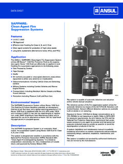
1 Featuresn Choice of four foam chamber sizes for various foam solution flow rate requirementsn Hinged inspection hatch with captive bolt securement for ease of inspection and maintenancen Choice of carbon steel or 304 stainless steel with corrosion resistant (CR) epoxy paint finishn TEFLON* vapor seal allows unrestricted flow of expanded foamn Convenient vapor seal replacement without removal of retaining boltsn UL ListedApplicationANSUL foam chambers are air-aspirating foam discharge devices that are used to protect various types of flammable liquid storage tanks including open top floating roof tanks and cone roof tanks with or without internal floaters. Additional applications include most types of open tanks where flammable liquid products are chambers are defined by NFPA 11 as Type II discharge outlets for delivering foam to the surface of a flammable liquid.
2 They are commonly used with bladder tanks, balanced pressure pump proportioning systems, line proportioners, or foam trucks. These foam chambers can be used with Ansul low-expansion foam agents that are determined to be suitable for the flammable liquid being Ansul foam chambers consist of a foam expansion chamber and an integral foam maker with a stainless steel screened air inlet. Each chamber includes an orifice plate, two inlet gaskets, vapor seal assembly, cover gasket, and an outlet gasket. The required deflector (split or shallow) and optional mounting pad assembly are sold removable orifice plate located at the flanged inlet to the foam maker is sized to deliver the required flow rate of foam solution at a specified inlet pressure. A frangible TEFLON vapor seal is burst upon entry of foam solution allowing an un restricted flow of expanded foam into the chamber body.
3 From the chamber body, the foam flows through the foam deflector which disperses the foam into the storage chamber vapor seal is accessible for inspection and service through a hinged inspection hatch that is secured with captive bolts. The hatch also contains a lifting handle that is designed to support the weight of the foam foam deflector directs the foam stream down the tank side-wall to lessen the submergence of the foam and agitation of the fuel surface (Type II application). The foam deflector is a split (two-piece) style. The split deflector allows for either bolting or welding to storage tanks when installation may be performed from both sides of the tank wall as with newly constructed tanks. The split deflector also allows for insertion of the deflec-tor through the flange opening from the outside wall as is often required with tanks already in foam chamber and deflector can be bolted to the storage tank using a mounting pad.
4 The pad contains mounting studs to fit standard flange RangeThe flow rate of the foam chamber is determined by the orifice size and the inlet pressure. The flow ranges listed in the following table are based on 40 psi ( bar) using the smallest orifice for the minimum flow and 100 psi ( bar) using the largest orifice for the maximum flow. K-Factor Model Typical Flow Range RangeAFC-90 49 gpm to 151 gpm to (185 Lpm to 572 Lpm)AFC-170 94 gpm to 279 gpm to (356 Lpm to 1,056 Lpm)AFC-330 183 gpm to 610 gpm to (693 Lpm to 2,309 Lpm)AFC-550 350 gpm to 980 gpm to (1,325 Lpm to 3,709 Lpm)UL Listed flow ranges vary by foam concentrate consult the UL Online Certifications Directory for agent-specific flow ranges. To determine flow rates for specific applications and proper orifice sizing, consult Johnson Controls Technical Stanton Street | Marinette, WI 54143-2542, USA | +1-715-735-7411 | 2018 Johnson Controls.
5 All rights reserved. All specifications and other information shown were current as of document revision date and are subject to change without notice. | Form No. F-85154-11 DATA SHEETS pecificationsThe foam chamber assembly shall consist of a chamber body with an integral foam maker and orifice plate. Each chamber shall include an orifice plate, two inlet gaskets, vapor seal assembly, cover gasket, and an outlet gasket. A foam deflector and foam chamber mounting pad shall be available for use with the assembly as foam chamber body shall be of steel construction with a CR epoxy finish. The discharge outlet shall be of the flat faced flange design that may be welded or bolted to the storage tank. For ease of access to the vapor seal, the chamber body shall contain a hinged inspection hatch secured with stainless steel captive bolts.
6 The hatch shall also contain a lifting handle designed to support the weight of the chamber for foam maker shall contain a stainless steel screen that is cylindrically shaped to conform to the air inlet surface to help prevent damage. The vapor seal shall be of TEFLON construction to allow an unrestricted flow. The TEFLON vapor seal shall be designed of a thickness to meet the UL required flowing foam solution burst pressure range of 10 psi to 25 psi ( bar to bar). The vapor seal retainer shall be designed with slotted keyholes to eliminate bolt removal during replacement. The inlet to the foam maker shall be a raised face flange with an orifice sized to allow the required flow rate of foam solution at the available split foam deflector shall be provided for either bolting or welding to the mounting surface, or for installation from the outside wall of the storage tank.
7 For bolting applications, a mounting pad shall be available with a stud pattern compat-ible with the flat-face flange of the foam chamber body and the foam stainless steel nameplate shall be attached to the foam chamber hatch. The nameplate shall specify manufacturer, model number, and part BODYOUTLETFLANGEINLETFLANGEGASKETSMOUNTI NGPADORIFICEPLATEGASKETSSPLITDEFLECTORTA NK WALL001257 Dimension TableDimension AFC-90 AFC-170 AFC-330 AFC-550 A 26 1/16 in. 31 7/8 in. 35 3/8 in. 42 in. (662 mm) (810 mm) (899 mm) (1,067 mm) B 15 5/16 in. 19 5/8 in. 20 5/8 in. 24 3/4 in. (389 mm) (498 mm) (524 mm) (629 mm) C 8 1/2 in. 10 in. 11 1/8 in. 12 3/8 in. (216 mm) (254 mm) (283 mm) (314 mm) D 8 5/8 in. 10 3/4 in. 12 3/4 in. 16 in. (219 mm) (273 mm) (324 mm) (406 mm) E 7 in. 9 in. 10 in. 12 in. (178 mm) (229 mm) (254 mm) (305 mm) Fi 2 1/2 in.
8 3 in. 4 in. 6 in. (64 mm) (76 mm) (102 mm) (152 mm) Fo 4 in. 6 in. 8 in. 10 in. (102 mm) (152 mm) (203 mm) (254 mm) G 3 1/4 in. 4 1/16 in. 5 in. 6 7/8 in. (83 mm) (103 mm) (127 mm) (175 mm) H 5 5/16 in. 7 3/8 in. 9 1/8 in. 9 3/4 in. (135 mm) (187 mm) (231 mm) (248 mm) I 8 in. 9 1/2 in. 11 in. 12 in. (203 mm) (241 mm) (279 mm) (305 mm) J 4 5/8 in. 6 1/8 in. 7 3/4 in. 8 1/4 in. (117 mm) (156 mm) (197 mm) (209 mm) K 8 in. 12 in. 16 in. 20 in. (203 mm) (305 mm) (406 mm) (508 mm) L 12 in. 18 in. 24 in. 30 in. (305 mm) (457 mm) (610 mm) (762 mm) M 4 1/2 in. 6 5/8 in. 8 5/8 in. 10 3/4 in. (114 mm) (168 mm) (219 mm) (273 mm) N 7 1/2 in. 9 1/2 in. 11 3/4 in. 14 1/4 in. (191 mm) (241 mm) (298 mm) (362 mm) O 3/4 in. 7/8 in. 7/8 in. 1 in. (19 mm) (22 mm) (22 mm) (25 mm) P 2 7/8 in. 3 1/2 in.
9 4 1/2 in. 6 5/8 in. (73 mm) (89 mm) (114 mm) (168 mm) Q 5 1/2 in. 6 in. 7 1/2 in. 9 1/2 in. (139 mm) (152 mm) (191 mm) (241 mm) R 3/4 in. 3/4 in. 3/4 in. 7/8 in. (19 mm) (19 mm) (19 mm) (22 mm) S 8 1/2 in. 12 in. 16 in. 20 in. (216 mm) (305 mm) (406 mm) (508 mm) T 14 1/2 in. 16 in. 24 1/2 in. 23 1/4 in. (368 mm) (406 mm) (622 mm) (590 mm) U 1 1/2 in. 1 1/2 in. 1 1/2 in. 3 5/16 in. (38 mm) (38 mm) (38 mm) (84 mm) V 6 15/16 in. 8 25/32 in. 10 27/32 in. 13 3/4 in. (176 mm) (223 mm) (275 mm) (349 mm) W 4 5/16 in. 4 11/16 in. 5 3/4 in. 7 5/32 in. (110 mm) (119 mm) (146 mm) (182 mm) 009146 WELDING WITH SPLIT DEFLECTORBOLTING WITH PAD AND SPLIT DEFLECTORJABCDEIBOLTING WITH SPLIT DEFLECTORGFi INLET FLANGEFO OUTLET FLANGE008544 SHALLOW DEFLECTORS REQUIRE INSTALLATION FROM INSIDE OF THE TANKVS008543 BOLTING WITH SHALLOW DEFLECTORTUWRINLET FLANGE (Fi DETAIL) raised FACEAFC-330, AFC-550 AFC-90, AFC-170001260 RINLET FLANGE (Fi DETAIL) raised FACEQQPPHNote: The inlet and outlet flanges are designed to mate with ANSI 150 lb class , AFC-170, AFC-330 OOOUTLET FLANGE FLAT FACE (FO DETAIL)OUTLET FLANGE FLAT FACE (FO DETAIL)MMNN002158 Ordering InformationFoam ChambersNote: Flow rates and pressure levels at the inlet must be specified at the time of order.
10 Failure to supply this information may cause order delays. Approximate Shipping WeightPart No. Description lb (kg)75879 Foam Chamber/Maker, AFC-90, carbon steel , CR Epoxy Red 60 ( )445921 Foam Chamber/Maker, AFC-90, 304SS, CR Epoxy Red 60 ( )74376 Split Deflector, 90 Size, carbon steel , Primed 5 ( )428637 Shallow Deflector, 90 Size, carbon steel , Primed** 5 ( )443200 Split Deflector, 90 Size, 304SS, Primed 5 ( )443201 Shallow Deflector, 90 Size, 304SS, Primed** 5 ( )75880 Foam Chamber/Maker, AFC-170, carbon steel , CR Epoxy Red 100 ( )445922 Foam Chamber/Maker, AFC-170, 304SS, CR Epoxy Red 100 ( )74380 Split Deflector, 170 Size, carbon steel , Primed 10 ( )428638 Shallow Deflector, 170 Size, carbon steel , Primed** 10 ( )443202 Split Deflector, 170 Size, 304SS, Primed 10 ( )