Transcription of Datasheet - TDA7498E - 160-watt + 160-watt dual BTL class ...
1 PowerSSO-36exposed pad upFeatures 160-W + 160-W output power at THD = 10% with RL = 4 and VCC = 36 V 1 x 220 W output power mono parallel BTL at THD = 10% with RL = 3 andVCC = 36 V Wide-range single-supply operation (14 - 36 V) High efficiency ( = 85%) Parallel BTL function using the MODE pin Four selectable, fixed gain settings of nominally dB, dB, dB dB Differential inputs minimize common-mode noise Standby and mute features Smart protection Thermal overload protection Small offset less than 20 mVDescriptionThe TDA7498E is a dual BTL class -D audio amplifier with a single power supplydesigned for home systems and active speaker comes in a 36-pin PowerSSO package with exposed pad up (EPU)
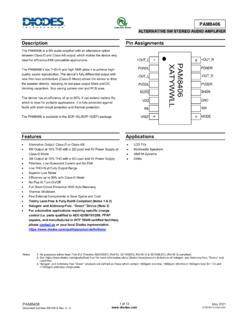
2 To facilitatemounting a separate status linkTDA7498 EDevice summaryOrder codeTDA7498 ETRO peratingtemperature range0 to 70 CPackagePowerSSO36(EPU)PackingTape and reel160-watt + 160-watt dual BTL class -D audio amplifierTDA7498 EDatasheetDS8807 - Rev 4 - June 2020 For further information contact your local STMicroelectronics sales block diagramThe figure below shows the block diagram of one of the two identical channels of the 1. Internal block diagram (showing one channel only)TDA7498 EDevice block diagramDS8807 - Rev 4page 2/172 Pin 2.
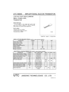
3 Pin connections (top view, PCB view) 1234567891011121314151617182829303132333 43536192021222324252627 VSSSUB_GNDOUTPBOUTPBPGNDBPGNDBPVCCBPVCCB OUTNBOUTNBOUTNAOUTNAPVCCAPVCCAPGNDAPGNDA OUTPAOUTPAPGNDVDDPWSTBYMUTEINPAINNAROSCS YNCLKVDDSSGNDDIAGSVRGAINMODEINPBINNBVREF SVCCEP, exposed padConnect to groundTDA7498 EPin descriptionDS8807 - Rev 4page 3 listTable 1. Pin description listNumberNameTypeDescription1 SUB_GNDPWRC onnect to the frame2,3 OUTPBOP ositive PWM for right channel4,5 PGNDBPWRP ower stage ground for right channel6,7 PVCCBPWRP ower supply for right channel8,9 OUTNBON egative PWM output for right channel10,11 OUTNAON egative PWM output for left channel12,13 PVCCAPWRP ower supply for left channel14,15 PGNDAPWRP ower stage ground for left channel16,17 OUTPAOP ositive PWM output for left channel18 PGNDPWRP ower stage (nominal)
4 Regulator output referred to ground for power stage20 STBYIS tandby mode control21 MUTEIMute mode control22 INPAIP ositive differential input of left channel23 INNAIN egative differential input of left channel24 ROSCOM aster oscillator frequency-setting pin25 SYNCLKI/OClock in/out for external (nominal) regulator output referred to ground for signal blocks27 SGNDPWRS ignal ground28 DIAGOOpen-drain diagnostic output29 SVROS upply voltage rejection30 GAINIGain setting input31 MODEIE nables stereo or mono BTL mode of operation32 INPBIP ositive differential input of right channel33 INNBIN egative differential input of right channel34 VREFOHalf VDDS (nominal) referred to ground35 SVCCPWRS ignal power (nominal)
5 Regulator output referred to power supply-EP-Exposed pad for heatsink, to be connected to groundTDA7498 EPin listDS8807 - Rev 4page 4/173 Electrical maximum ratingsTable 2. Absolute maximum ratingsSymbolParameterValueUnitVCCDC supply voltage for pins PVCCA, PVCCB, SVCC45 VVIV oltage limits for input pins STBY, MUTE, INNA,INPA, INNB, INPB, GAIN, to junction temperature0 to 150 CTopOperating ambient temperature0 to 70 CTstgStorage temperature-40 to 150 dataTable 3. Thermal j-caseThermal resistance, junction to operating conditionsTable 4.
6 Recommended operating conditionsSymbolParameterMinTypMaxUnitVC CS upply voltage for pins PVCCA, PVCCB, SVCC14-39 VTambAmbient operating temperature0-70 specificationsUnless otherwise stated, the values in the table below are specified for the conditions: VCC = 36 V, RL = 4 ,ROSC = R3 = 39 k , C8 = 100 nF, f = 1 kHz, GV = dB Tamb = 25 5. Electrical quiescent currentNo LC filter, no load-60mAIqSTBYQ uiescent current in standby--1 AVOSO utput offset voltageVi = 0, Av = dB, no load-20-20mVIOCPO vercurrent protection thresholdRL = 0 101114 ATjJunction temperature at thermalshutdown-140150160 CRiInput resistanceDifferential input69-k VUVPU ndervoltage protection threshold---8 VRdsONPower transistor on-resistanceHigh TDA7498 EElectrical specificationsDS8807 - Rev 4page 5 (Continued)RdsON(Continued)Power transistor on-resistanceLow side(Continued)
7 PowerTHD = 10%-160-WTHD = 1%-125-PoParallel BTL (mono) output power,RL = 3 ohm, Vcc = 36 VTHD = 10%-220-WTHD = 1%-170- Efficiency-85-%THDT otal harmonic distortionPo = 1 gainGAIN < * *VDD < GAIN < * *VDD < GAIN < * > * GVGain matching--1-1dBCTC rosstalkf = 1 kHz, Po = 1 W5060-dBVnTotal output noiseInputs shorted and to ground,A Curve231 VInputs shorted and to ground,f = 20 Hz to 20 kHz400 SVRRS upply voltage rejection ratiofr = 100 Hz, Vr = Vpp,CSVR = 10 F-55-dBTr, TfRise and fall times--35-nsfSWSwitching frequencyInternal oscillator240310400kHzfSWRO utput switching frequency rangeWith internal oscillator by changingROSC (1)240-kHzVinHDigital input high (H) input low (L) & mute & playSTBY < V; MUTE = XStandbySTBY > V; MUTE < LMuteSTBY > V; MUTE > HPlayAMUTEMute attenuationVMUTE < L, VSTBY = H-75-dB = 106 / ((16 * ROSC + 182) * 4) kHz, fSYNCLK = 2 * fSW with R3 = 39 k (see Figure 3.)
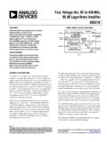
8 Test circuit stereo application andmono BTL mode). TDA7498 EElectrical specificationsDS8807 - Rev 4page 6 circuitFigure 3. Test circuit stereo application and mono BTL modeGAIN components or circuitryL+R+R-VCCGNDL+L-R+R-TDA7498 EMUTESTBY3V3 POWER SUPPLYS ingle-Ended InputCLASS-D amplifier For Single-Ended Input andLoad=4 ohmFor LOUTPUTINPUTL-MONOOUTFREQUENCY SHIFTLoad=4 ohmR-OUTPUTMONOOUT(PSSO36)MONO ConfigMONOC onfigMONOINPUTL+, L- OnlyMODE SETTINGSTEREOMONOMODE JUMPERJ5J6,J3, + + +C232200uF50VL3L1L2C1710uF10VC1610uF10VD 118VJ4C301uFC311uFR158RC28220nFR168RC242 20nFR178RC18220nFR188RC22220nFSYNC2413J1 R10100kR11100kR12100kJ11J12J5J10J3R339KC 8100nFR9180K123Q1 KTC3875(S)
9 R1347kR14100kD2D3D4D8D6D5D7D9+C322200uF5 0V12J1412J13WL+WR+WL-WR-L1SL2SL3SL4SR193 3kDIAGVDDSVDDSVDDSVCCVCCVCCVCCVCCVDDS3V3 PSPSTDA7498 ETest circuitDS8807 - Rev 4page 7/174 Characterization curvesUnless otherwise stated the measurements were made under the following conditions:VCC = 36 V, f = 1 kHz, GV = dB, ROSC = 39 k , COSC = 100 nF, Tamb = 25 RL = 4 , stereo configurationFigure 4. Output power vs. supply voltageFigure 5. THD vs. output powerFigure 6. THD vs. frequencyFigure 7. FFT performanceFigure 8. Crosstalk vs. frequencyTDA7498 ECharacterization curvesDS8807 - Rev 4page 8 RL = 3 , mono BTL configurationFigure 9.
10 Output power vs. supply voltageFigure 10. THD vs. output powerFigure 11. THD vs. frequencyTDA7498 EFor RL = 3 , mono BTL configurationDS8807 - Rev 4page 9/175 Application and mono BTL operation selection using the MODE pinThe TDA7498E can be used in stereo applications or mono BTL applications. Connecting the MODE pin to theVDDS pin configures the device in mono BTL. The output of the two channels can be paralleled. When the MODEpin is connected to ground or floating (pulled down internally) the device works as a stereo settingThe gain of the TDA7498E is set by GAIN (pin 30).