Transcription of DEALER/INSTALLER: GIVE TO HOMEOWNER …
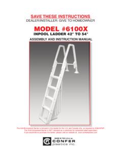
1 MODEL #7100 EVOLUTION A-FRAME LADDERFOR RIGID-FRAMED POOLS ONLYASSEMBLY AND INSTALLATION MANUALMade in bySAVE THESE INSTRUCTIONS DEALER/ installer : give TO HOMEOWNERThe Anti-Entrapment Barrier is included in this ladder for the and Canada only, as required by ANSI/APSP requirements. The Anti-Entrapment Barrier is NOT intended as a substitute for competent adult you would like to purchase the barrier, please visit our website at: LegTread ConnectorSwing UpTreadUpper BraceStandard TreadExtensionBootLower BaseLargeBarrierSmallBarrierHardware Pack4 - 1/4 - 20 x 2" Bolt4 - 1/4 - 20 Acorn Nut2 - #10 x 1-1/4" Screw2 - 1/4 - 20 x 2-1/4" Bolt2 - 1/4 Flat Washer2 - 1/4 - 20 Hex Nut4 - Plug (white)1 - PadlockTools Needed for Assembly* - Hammer or mallet* - Phillips Screwdriver* - Adjustable wrench* - Liquid soap or lubricant* - Battery operated drill motor* - 5/16 Drill bitBarrier Parts List (if included)(Included in Hardware Pack)4 - #10 x 1-1/4 screws1 - Strip of 4 Foam Pads1 - Large Barrier Section1 - Small Barrier Section1 - Upper Brace1 - Lower BaseModel #7100 EVOLUTION A-FRAME LADDERA djustable to fit 48 to 54 Rigid-Framed Above Ground PoolsASSEMBLY INSTRUCTIONS - PLEASE READ BEFORE ATTEMPTING ASSEMBLYP arts List4 - Ladder Legs2 - Tread Connectors4 - Swing Up Treads6 - Standard Treads4 - Extension Boots1 - PlatformIf missing parts call - Toll free - 866-396-2968 or *NOTE: If you are using this ladder on a 48 pool you will not use the extension boots.
2 Proceed to # the roundplastic inserts,on the sides ofthe extensionboots, are stillin place,remove themwith a phillipshead screw-driver the four extensionboots over the ends ofthe assembled ladderslegs. They will need tobe all the way on formost 52 tall pools andbacked off one hole for54 pools. Dependingupon ground levels out-side the pool, and sandlevels under the linerinside the pool, a finaladjustment may needto be made after theladder is put into four 1/4-20 x 2 long bolts andfour acorn nuts fasten the extensionboots to the ladder legsRemove the keyhole slot insertsfrom two of the ladder the end of oneof the standard treadsinto the uppermostkeyhole slot. Makesure that the treadand the ladder leg arepositioned as shownin the photographabove. It may be nec-essary to tap the treadinto the slot with amallet. Repeat forthree the platform down until it is fully seatedon the lugs of the legs as shown. Using a #10 x 1-1/4 screw fasten theupper ends of the ladder legs together as shown.
3 Repeat for opposite one of the ladder legs to theopposite ends of the four standard treadsmaking sure that the curved upper endsare both facing in the same the treads downward so thatthey seat fully into the bottom of thekeyhole the ladder leg down onto the ends ofthe sure that the swing-up side of the plat-form is facing away fromthe inside ladder section,as shown, slip the open-ings of the platform overthe upper ends of the lad-der legs. Using a mallet orhammer tap the platformdown until it is fully seatedonto the nubs of the lad-der legs. Liquid soap orlubricant will help the partsslide the othertwo ladder legsthrough theopenings of theplatform untilthey engage theother ladder legsas shown in next screws the tread connector as shown,with the padlock hole facing upward, andtap it over the round knob. Repeat for theopposite tread the tread connectors onto the endsof the treads until they are firmly the four swing up treadsonto the ladder legs as the two remaining standardtreads to the extension boots (or directlyto the ends of the ladder legs if installingon a 48 tall pool).
4 Snap Small and Large Barrier Sectionsinto slots on Lower Base as Barrier sections at the topslightly and position Upper Brace overSmall Barrier Section. Next, spread the fingers on the Upper Brace and slideinto position on the Large Barrier the Base and Brace into position, centered,on the bottom and fourth treads of the the four (4) #10 x 1-1/4" screws (included inhardware pack) on a slight angle, first in theUpper brace, then in the Lower Base. Install theself-adhering foam strips to the Large BarrierSection as shown in Swing up portion of ladder shownin down position and the padlockin the holding up portion of ladder shown in up position, secured with Ladder did notinclude Barrier, skip steps 18 through 20. Continue to step ACCESSORYSKIM-ITSKIMS OFF DEBRIS Cut cleaning time 75% with skimmerextension that guides debris directly into your skimmer. Fits most in-ground and above-ground pool skimmers. Corrosion-resistant plastic Skim-It installs in seconds without CONVERSION KITTo easily convert your ladder to a deck ladder order our #CK7100.
5 The conversion kit includes all parts and hardware needed. Check foravailability at your local pool dealer or order online at : To winterize your ladder pull the ladderfrom the pool, remove the plugs, lay the ladder on itsside to allow the water to drain out. A small amount ofwater left in the ladder will not cause any the plugs into the fill holes so that they do notget lost. The ladder may be left PREVENT FLOATINGFill the inner ladder legs with water and cover thefour fill holes with plugs. Place the ladder over thepool top seat with the swing up treads on the outside of the pool. Tip the ladder sideways toallow the treads to fill the water. This will preventfloating. The platform should rest on the pool topseat and the bottom tread should rest firmly on thepool bottom. If they do not, the extension bootsmay be adjusted up or down as required to achieve the best maximum stability, the ladder should be fas-tened to the top of the pool.
6 Postion the ladder atthe desired location on the pool top seat and markthe two locations of the holes in the platform ontothe top seat. Move the ladder away, and beingcareful not to drill into the liner, drill two holesthrough the top seat. Fasten the ladder to the topseat using two 1/4-20 x 2-1/4 bolts, 1/4 flat wash-ers, and 1/4-20 hex : WHENEVER THE POOL IS NOT IN USE THE OUTER TREADS MUST BE IN THE UP POSITION AND LOCKED WITH THE INCLUDED Witmer RoadNorth Tonawanda, New York 14120-2421 Toll Free 866-396-2968716-283-1826/ FAX in IN THE by:6CP-7100B 15M 10/07 CONFER PLASTICS, , PRO-RATED WARRANTYC onfer Plastics, Inc. warrants their swimming pool ladders to be free from defects in workmanship for one year fromdate of purchase. After the first year the cost to replace a part is as follows:MODEL #71002ndYear - 20%3rdYear - 40% 4thYear - 60%5thYear - 80%Plus shipping/handlingEnclose proof-of-purchase (receipts, etc.) showing date purchased, your name, address, and daytime phone number.
7 Youwill be notified of cost to replace warranty gives you specific legal rights, and you may also have other rights which may vary from state to NOT RETURN DEFECTIVE PART TO DEALERThe defective part should be returned, postpaid, to:Confer Plastics, Witmer RoadNorth Tonawanda, 14120-2421of current partslist priceIMPORTANTFOR YOUR SAFETY* Check the contents of the carton with the Parts listfor this ladder.*If any parts are missing call Toll Free - 866-396-2968 or visit our web site *DO NOTattempt to assemble or install the ladderif there are ANYshortages of parts or hardware.*For proper assembly and installation follow allinstructions in the sequence shown.*Before using the product, after assembly and installation, go over the instructions and proceduresagain to make sure nothing has been overlooked.*Be sure and safe. The manufacturer IS NOTresponsible for improper assembly, installation and RULES*Locate ladder on a solid base.*One person on the ladder at a time.
8 *Ladder MUSTbe installed per manufacturer s instructions.*DANGER:No Jumping or Diving from ladder.*Face ladder when entering and leaving pool.*To prevent entrapment or drowning DO NOTswim through, behind or around ladder.*Ladder to be used as a swimming pool ladder only.*Weight limit - 300 lbs maximum*Warning:Exceeding the maximum weight restriction may cause the ladder to fail.*When ladder is not in use lock up outer treads with padlock provided in hardware bag.*Consult your local Building Department beforeinstallation of your pool and equipment.*DANGER:Use a cordless drill for assembly and installation. NEVER use an electric drill in or around the pool.