Transcription of Defect and mould variable prediction in …
1 CAMISANI-CALZOLARI, ER., CRAIG, , and PISTORIUS, Defect and mould variable prediction in continuous casting . Application of Computers and Operations Research in the Minerals Industries, South African Institute of Mining and Metallurgy, 2003. Defect and mould variable prediction in continuous casting CAMISANI-CALZOLARI*, CRAIG*, and PISTORIUSt *Department of Electrical, Electronic and Computer Engineering, University of Pretoria, Pretoria, South Africa tDepartment of Materials Science and Metallurgical Engineering, University of Pretoria, Pretoria, South Africa Defects which occur at the surface of a continuously cast slab impede the throughput of final product, because an extra stage in the process is required to grind the defects away before further processing can take place. Defect prediction and the minimization of the occurrence of defects is required.
2 The use of two models to define the Defect propagation is explained. Both models are derived using system identification techniques such as auto-regression with exogenous input (ARX). One model is used to determine the effect of manipulated variables such as casting speed and measured disturbances such as mould level on temperatures within the mould . The other is used to determine or indicate the effect of the mould temperatures on the occurrence of defects such as transversal cracks. The latter model can be used to predict when the defects will occur and the former can be used to control the occurrence of the defects. Keywords: continuous casting , surface Defect , control system, predictor, system identification, ARX Introduction The continuous casting process forms part of steel-making and is the predominant method for the solidification of molten steel into large blocks known as slabs.
3 The primary extraction of energy from the molten steel takes place in the mould of the continuous caster. This phase of solidification is considered to be instrumental in the genesis of defects that are present at the surface of the cast product (see Graebe et aP). The defects that occur are detected by human operators only after the slab has cooled down enough after casting has been completed-several hours after casting commenced. This is a necessary step because defects can cause serious product quality problems and have to be removed. The surface of the slab is grinded to remove any surface defects that may occur, and is inspected once again to ensure that deep-lying defects are not present. If further defects are present, the slab is spot grinded to remove these deep-lying defects. The net effect is that grinding causes a very long delay between the completion of casting and further processing such as rolling.
4 If the grinding phase can be excluded from the global process, then hot charging (Wiesinger et and Holleis et aP) or direct rolling become possible. During hot charging, the cast product is sent for rolling before the slab cools off below 650 C (Wiesinger et ); thus reducing the time required for re-heating of the slab before it can be rolled and minimizing the cost of energy required. For direct rolling, the casting process and slab scheduling is optimized to such an extent that the slabs are directly sent for rolling, thus eliminating the energy and time required at the re-heating furnace. Direct rolling is, however, impossible if the extent of surface defects is so severe that post- casting treatment ( grinding) of the slab is required. The grinding treatment cannot be done at the elevated temperatures which are required for hot rolling (circa 1150 C [Wiesinger et ]) and thus the throughput of the product is reduced due to the time required to cool, treat and reheat the cast slab.
5 The cost of energy consumed in the reheating furnace also implies unnecessary financial losses. If hot charging (rather than direct rolling) is practised, surface treatment does not appear to imply as great a loss, since some reheating is required whether surface treatment is applied or not. However, the time that surface treatment takes implies a reduction in throughput. The need for higher throughput of cast product has prompted the authors to investigate the possibility of using control system techniques to reduce or even eradicate the occurrence of defects. Once defects have been eliminated, direct rolling may become possible, because the intermediate step of grinding is eliminated. This paper presents results based on the use of system identification techniques as a modelling tool to predict and control the occurrence of defects.
6 A brief overview of the process will be given, and the main fundamentals of system identification utilised here will be explained. A model structure has been defined and will be repeated. The application of system identification to derive a predictor model and a mould model will be perused, and results of the models will be shown to verify that the model can be used. Finally, some conclusions will be given. Background The following sub-sections are necessary to understand the process at hand. Process The pre-treatment of steel involves melting of iron together Defect AND mould variable prediction IN continuous casting 253 with catalysts, removal of chemical elements such as sulphur and addition/removal of elements such as carbon, The steel is heated to high temperatures to effect the right composition of the steel grade that is desired by the customer, The steel must be presented in solid form at room temperature to the client, either as solidified slabs (typically 200 mm thick, 1000 to 1600 mm wide and 5000 to 12000 mm long) or rolled plate, To present the solid steel to the client, the molten steel must first be cooled.
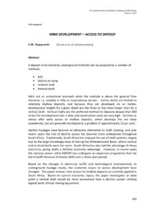
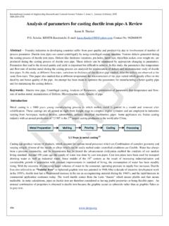
7 The continuous casting process is used to achieve this goal in almost all steel-making plants in the world. The steel arrives in its molten state at the caster in a container known as a ladle (see Figure 1). The ladle feeds a tundish through constant flow and the tundish feeds the mould in turn through constant flow, The addition of an extra steel container (tundish) is primarily to achieve the 'continuity' of the process so that when a ladle is empty, the tundish still has some steel left and can continue the casting process in the mould without interruption. The mould is the most vital component of the process and is said to be the initiator of most defects. It is an open-ended, water-cooled, copper-sheath and extracts the most energy from the molten steel during the casting process, As steel moves down the mould it solidifies*, ensuring that at the bottom of the (typically 1 m long) mould there is a thick enough solid shell of steel to withstand ferro-static pressures of the liquid steel contained within.
8 Once out of the mould , the strand is cooled over approximately five metres by water sprays impinging directly on the smface of the strand. As the strand moves out of the water-spray area, it is cut and sent for further processing to grinders and then to rolling mills or directly to the customer after it has cooled appropriately. *To prevent sticking, the mould oscillates at low frequency and stroke to aid the removal of the strand . mould Cooling Zone ___ +-<0-Defects Typical surface defects that may occur are cracks, either transversally (Mintz et ) or longitudinally (Brimacombe et , Kim et , Moiseev et , Nakajima et ) to the direction of casting , and inclusions (Bouris and Bergeles10) of non-metallic elements such as the lubricating powder that is used to aid in the reduction of friction between the copper mould wall and steel surface.
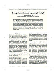
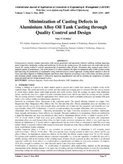
9 Other defects that occur are depressions (non-rectangular form of the slab, Thomas et ) and oscillation marks (King et , Spaccarotella et ) due to the oscillating motion of the mould and bleeder (Kumar et ) marks due to temporary 'welding' of the steel surface to the copper sheath, Further explanation of the characteristics and formation of defects will be excluded here but can be found in the referenced texts above. General model As stated in the introduction, the need has arisen to be able to detect and control the occurrence of defects in the continuous casting process. This can be achieved using input/output modelling in which monitored or controlled variables* in the process are the inputs and the defects are the outputs. Due to the genesis of defects within the mould , only input variables within the mould will be considered, Other variables (such as secondary cooling zone spray patterns) act as disturbances on the system (Camisani-Calzolari et aL 4).
10 A graphical representation of the input/output model structure with these facts taken into consideration is given in Figure 2. The inputs consist of manipulated variables, measured and unmeasured disturbances and variables which do not fall within either of the mentioned categories. The controlled inputs consist of casting speed and the frequency of oscillation of the mould . Disturbances which can be measured are the level of liquid metal in the mould and the *Such as the speed at which casting takes place Ladle Tundish ) mould ')-----~\; Rollers S/ ~ ~--=-_ S<m,d ~~ -"-'-____ casting Direction-Secondary Cooling Zone ____ .. (>~ --Radiation Cooling Zone-------------;:------------Figure 1. The bow-type continuous caster. Adapted from Camisani-Calzolari et 254 APCOM2003 INPUTS Manipulated variables: casting speed Oscillation Frequency Measured disturbances: mould level Water temperature Unmeasured disturbances: Superheat mould powder Steel flow-rate Other measured variables 40 Thermocouples 4 Water Flow-rates 4 Temperature Distributions 4 Heat Flows 20 Temperature gradients Other disturbances D continuous Caster OUTPUTS Surface defects Figure 2.