Transcription of DEFLECTION OF CONCRETE FLOOR SYSTEMS FOR …
1 Technical Note Your Partner in Structural CONCRETE Design TN292_Floor_deflection_032109. DEFLECTION OF CONCRETE FLOOR SYSTEMS . FOR SERVICEABILITY1. Bijan O Aalami2. DEFLECTION control is a central considerations in serviceability of FLOOR SYSTEMS . This Technical Note reviews the levels of acceptable deflections and the currently available methods for their estimate. OVERVIEW.. There are several reasons to control DEFLECTION . A CONCRETE FLOOR should have adequate stiffness to prevent changes in DEFLECTION that would damage attached partitions or other construction elements likely to be damaged by large deflections. The DEFLECTION of a FLOOR should not be noticeable by occupants such as to convey a sense of inadequacy or safety concerns. Since, in some instances, DEFLECTION is used as a measure leading of undesirable vibration in a FLOOR , its value must be controlled. LIMITS FOR ACCEPTABLE DEFLECTION . Aesthetics and Sense of Comfort In considering aesthetics and sense of comfort for occupants, the most important criterion is the out-of- level condition of a FLOOR , as opposed to its stiffness.
2 Sensitive individuals, when walking over or viewing a FLOOR in elevation, are claimed to perceive a FLOOR 's sag when the vertical out-of-level to span ratio is in excess of 1/250, and for cantilevers in excess of 1/125. The out-of-level condition of a FLOOR system can be controlled through camber at the time of construction, upon estimating the long-term DEFLECTION . DEFLECTION Limits to Mitigate Damage to Non-structural Construction It is important to note that ACI [ACI 318, 2008] does not impose a limit to DEFLECTION under selfweight. ACI's recommendations address the amount of DEFLECTION subsequent to the installation of non- structural elements likely to be damaged. The following table lists the ACI's stipulation on deflections (TABLE (b)). In the application of ACI's recommended DEFLECTION limits, it is important to recognize that the given values are to be compared with computed values, not measured out-of-plane amounts.
3 TABLE 1 MAXIMUM PERMISSIBLE COMPUTED DEFLECTIONS. 1. Copyright ADAPT Corporation, 2008. 2. Professor Emeritus, San Francisco State University; Principal, ADAPT Corporation ADAPT Corporation, Redwood City, California, USA, Tel: (650) 306-2400 Fax (650) 306 2401. ADAPT International Pvt. Ltd, Kolkata, India, Tel: 91 33 302 86580 Fax: 91 33 224 67281. Technical Note DEFLECTION Type of member DEFLECTION to be considered limitation Flat roofs not supporting or attached to nonstructural elements likely to be Immediate DEFLECTION due to live load L/180 *. damaged by large DEFLECTION Floors not supporting or attached to nonstructural elements likely to be Immediate DEFLECTION due to live load L/360. damaged by large DEFLECTION Roof or FLOOR construction supporting or attached to nonstructural elements likely L/480 **. That part of the total DEFLECTION occurring to be damaged by large DEFLECTION after attachment of nonstructural elements(sum of the long-time DEFLECTION due to all sustained loads and the immediate Roof or FLOOR construction supporting or DEFLECTION due to any additional live load)**.
4 Attached to nonstructural elements not L/240 **. likely to be damaged by large DEFLECTION Notes: * Limit not intended to safeguard against ponding. Ponding should be checked by suitable calculations of DEFLECTION , including added deflections due to ponding of water, and considering long-term effects of all sustained loads, camber, construction tolerances, and reliability of provisions for drainage. ** Limit may be exceeded if adequate measures are taken to prevent damage to supported or attached elements. ** But not greater than tolerance provided for nonstructural elements. Limit may be exceeded if camber is provided so that total DEFLECTION minus camber does not exceed limit. ** Long-time DEFLECTION shall be determined using established procedures, but may be reduced by amount of DEFLECTION calculated to occur before attachment of nonstructural elements. This amount shall be determined on basis of accepted engineering data relating to time- DEFLECTION characteristics of members similar to those being considered.
5 DEFLECTION CONTROL THROUGH LIMITATIONS ON SPAN TO DEPTH RATIOS. For common residential and commercial buildings, designers can forego DEFLECTION calculation, if the stiffness of the member selected is large enough. DEFLECTION calculation requirements are governed through recommended span-to-depth ratios for different types of FLOOR members. ACI 318 has the recommendations given in Tables 2 and 3. 2. Technical Note One-Way Conventionally Reinforced Slabs and Beams TABLE 2 MINIMUM THICKNESS OF CONVENTIONALLY. REINFORCED BEAMS OR ONE-WAY SLABS. Simply One end Both ends Member Cantilever supported continuous continuous Solid one-way slabs L/20 L/24 L/28 L/10. Beams or ribbed L/16 L/21 L/8. one-way slabs Notes: L =span length Values given shall be used directly for members with normal weight CONCRETE and Grade 60 ksi (400 MPa) reinforcement. For other conditions, the values shall be modified as follows: a) For lightweight CONCRETE having equilibrium density, wc, in the range of 90 to 115 lb/ft3 (1440-1840 kg/m3), the values shall be multiplied by ( wc).
6 But not less than [in SI units, ( c) but not less than 1, where c is the density in kg/m3]. b) For fy other than 60,000 psi(400 MPa), the values shall be multiplied by ( +fy/100,000) [in SI units ( +fy/670)]. Two-Way Conventionally Reinforced Slabs and Beams TABLE 3 MINIMUM THICKNESS OF SLABS WITHOUT INTERIOR BEAMS*. Without drop panels** With drop panels**. fy Interior Exterior panels Interior Exterior panels panels panels psi** Without With With Without edge edge edge edge beams beams beams** beams**. 40,000 Ln/33 Ln/36 Ln/36 Ln/36 Ln/40 Ln/40. 60,000 Ln/30 Ln/33 Ln/33 Ln/33 Ln/36 Ln/36. 75,000 Ln/28 Ln/31 Ln/31 Ln/31 Ln/34 Ln/34. Notes: * For two-way construction, Ln is the length of clear span in the long direction, measured face-to-face of supports in slabs without beams and face-to-face of beams or other supports in other cases. ** For fy between the values given in the table, minimum thickness shall be determined by linear interpolation.
7 ** Drop panels are defined as extension of slab thickening into span not less than span/6, and extension of thickening below slab not less than slab thickness/4. 3. Technical Note ** Slabs with beams between columns along exterior edges. The ratio of edge beam stiffness to the stiffness of the edge beam's design strip shall not be less than Post-Tensioned Members For post-tensioned beams and slabs, the recommended values by the Post-Tensioning Institute [PTI, 1990 are as follows: TABLE 4 RECOMMENED SPAN TO DEPTH RATIOS FOR. POST-TENSIONED MEMBERS. Continuous Simple Spans Spans Roof FLOOR Roof FLOOR One-way solid slabs 50 45 45 40. Two-way solid slabs (supported 45-48 40-45. on columns only). Two-way waffle slabs (1m pans) 40 35 35 30. Beams 35 30 30 26. One-way joists 42 38 38 35. Note: The above ratios may be increased if calculations verify that DEFLECTION , camber, and vibrations are not objectionable. DEFLECTION CALCULATIONS.]
8 Under otherwise unchanged conditions, the deformation of an exposed and loaded CONCRETE member continues to increase. The increase is due to creep under applied load and shrinkage from loss of moisture. The engineering approach to estimating of DEFLECTION is to determine the instantaneous response of a structure under an applied load, and magnify the instantaneous displacement due to the time-dependent factors of creep and shrinkage. With time, the rate of change in displacement reduces. For building structure it is assumed that five years is sufficient time for the deflections to have reached their final values. While it is practical to calculate the time-dependent DEFLECTION for any time interval, the common practice is to estimate the total value at five years and use this value in the design. Instantaneous DEFLECTION Instantaneous DEFLECTION is generally calculated using CONCRETE 's modulus of elasticity at 28 days, gross-cross sectional area and linear elastic theory.
9 The calculated DEFLECTION may require adjustment, if the member is likely to crack, when subjected to the design load. Cracking reduces the stiffness of a member and results in increased DEFLECTION . The options for calculating instantaneous DEFLECTION with due allowance to cracking are: Closed form formulas or tables, available primarily for uncracked sections;. Use of equivalent moment of inertia (Ie) and simplified averaging (ACI-318's simplified procedure);. Use of equivalent moment of inertia (Ie) combined with numerical integration; and Use of Finite Element FLOOR programs that allow for cracking. Each of the above procedures is briefly discussed in the following section. 4. Technical Note Closed Form Formulas Closed form formulas are readily available for beams and one-way slabs. The variables that describe the geometry of a two-way panel within a FLOOR system , however, are so extensive that it becomes impractical to compile a meaningful set of tables or relationships without extensive approximation.
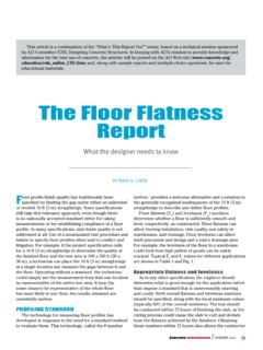
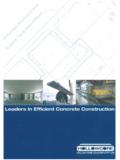
10 For non-cracked sections, compilations such as the one listed in Table 5 are readily available in the literature [Bares, 1971]. In the application of data, such as those given in Table 5, the design engineer must use judgment regarding the degree of fixity of the support. TABLE 5 DEFLECTION COEFFICIENTS k a b . 1. 2. 3 4. 1 Notes: Poisson's ratio conservatively assumed = a/b (aspect ratio). Boundary conditions 1 = rigid supports; rotationally free;. 2 = rigid supports; rotationally fixed;. 3 = central panel from an array of identical panels supported on columns;. DEFLECTION at center; and 4 = similar to case 3, but DEFLECTION at center of long span at support line w = k (a4*q / E*h3 ). Where, w = DEFLECTION normal to slab ;. a = span along X-direction;. E = Modulus of elasticity; and h = slab thickness. 5. Technical Note EXAMPLE 1. Consider the FLOOR system shown in Fig. EX-1. Estimate the DEFLECTION of the slab panel identified in part b of the figure under the follwoing conditions.