Transcription of DEHUMIDIFICATION STRATEGIES AND THEIR APPLICABILITY …
1 2018 Building Performance Analysis Conference and SimBuild co-organized by ASHRAE and IBPSA-USA Chicago, IL September 26-28, 2018 DEHUMIDIFICATION STRATEGIES AND THEIR APPLICABILITY BASED ON CLIMATE AND BUILDING TYPOLOGYABSTRACT DEHUMIDIFICATION is a highly energy intensive process, especially in humid climates and for building typologies that require strict space humidity setpoints. Sub-cooling of air to condense out moisture using chilled water or refrigerant is the most common method for dehumidifying. Alternative STRATEGIES such as desiccant wheel, dual wheel and wrap around coils could more energy efficiently be used for certain climate zones and project types. Using energy models and results from a customized Excel-based tool, this paper evaluates APPLICABILITY of each DEHUMIDIFICATION strategy based on the local climate and building typology.
2 INTRODUCTION Moisture indoors affects occupant comfort, the lifespan of building materials, and the operational effectiveness of program types that handle hygroscopic materials. In certain cases, the selection of mechanical equipment with thermally active surfaces also requires controlled space moisture levels to avoid the risk of surface condensation. Therefore, the ability to maintain strict humidity levels within a desired range by removing moisture from supply air is a critical aspect of air conditioning system design. The load on the cooling coil associated with removal of moisture that results from occupants, outside air (infiltration, ventilation air), and other processes which generate moisture, is called latent load. Space latent loads typically contribute to about 20-30% of the total building cooling load. Sensible Heat Ratio (SHR) is used as a metric to design mechanical cooling equipment.
3 A lower SHR corresponds to high latent gains and vice versa. = + (1) Traditionally, moisture removal is achieved by passing air over a chilled coil ( water , glycol, or refrigerant) and cooling it below its dew point temperature so the air releases moisture by condensing on the coil surface. This is an energy intensive process (cooling 1 lb of water by 1 F requires about 1 Btu of energy, while condensing 1 lb of water vapor to water requires about 1,000 Btu). This sub-cooling, in many instances, is then followed by re-heating the air up to the desired supply temperature. Depending on the specifics of the project, STRATEGIES such as desiccant DEHUMIDIFICATION , dual wheel systems, wrap around coils, and decoupling of sensible and latent loads, may show benefit in terms of annual energy use and reduced system size. To understand the APPLICABILITY of these STRATEGIES , THEIR effectiveness was studied by varying two key parameters: climate and building program type.
4 Multiple energy models and a spreadsheet tool developed by the authors, were used to perform the analysis. Based on the results from this analysis, this paper discusses the benefits and limitations of several such DEHUMIDIFICATION STRATEGIES and provides recommendations for early phase design considerations. DESCRIPTION OF STRATEGIES The following DEHUMIDIFICATION STRATEGIES , that have shown notable energy savings on existing projects, have been evaluated against a base case of a Dedicated Outdoor Air System (DOAS) with an enthalpy wheel, chilled water cooling coil, and heating hot water reheat. Desiccant DEHUMIDIFICATION Dual wheel system Wrap-around coil Tiered cooling ( chilled water for sensiblecooling, direct expansion for latent cooling)This section discusses the operating principles behind each aforementioned strategy and highlights the differences in how each dehumidifies outside air.
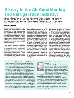
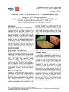
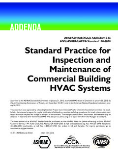
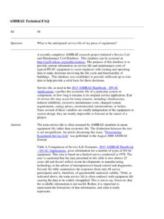
5 Jagan Pillai, , BEMP and Rushil Desai Atelier Ten, New York, NY 2018 ASHRAE ( ) and IBPSA-USA ( ). For personal use only. Additional reproduction, distribution, or transmission in either print or digital form is not permitted without ASHRAE or IBPSA-USA's prior written chilled water Cooling and DEHUMIDIFICATION The most common process for DEHUMIDIFICATION is to use a chilled water cooling coil. Figure 1 shows the system schematic and psychrometric chart showing the cooling and DEHUMIDIFICATION process. Outdoor air, after exchanging energy with exhaust air (1-2) passes over the cooling coil to cool the air down to the required leaving air humidity ratio (2-3) and then is reheated to the required supply air temperature (3-4). Desiccant DEHUMIDIFICATION In this process, a desiccant is used to remove moisture from air. Figure 2 shows the schematic and the psychrometric process for a desiccant DEHUMIDIFICATION system with an active desiccant wheel.
6 Outside air, after passing through an enthalpy recovery wheel (1-2), passes over a pre-cooling coil to reduce the air temperature (2-3); pre-cooled air then blows through a desiccant DEHUMIDIFICATION wheel where it goes through an isenthalpic process (3-4). During this process the moisture content of the air reduces and increases temperature. The high temperature air then passes over a post-cooling coil to cool it down to the required supply air temperature (4-5). This process, if optimized, can have a lower cooling load compared to the base case. Desiccant DEHUMIDIFICATION systems have the capability to dry the air to any desired humidity level, which is an advantage for certain applications. The limitation of this system is the need for high grade heat (about 180 F) to regenerate the desiccant. Thus, the best fit for this system is if the space needs to be maintained at a low (<50%) relative humidity or if there is a source of waste heat available to regenerate the desiccant.
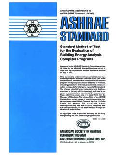
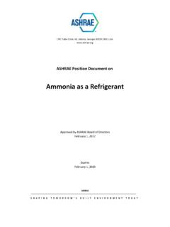
7 Figure 1 chilled water cooling/ DEHUMIDIFICATION : Schematic & Psychrometric chart Figure 2 Desiccant DEHUMIDIFICATION : Schematic & Psychrometric chart Dual Wheel System with Cooling Coil In this process, an additional, sensible heat recovery wheel is introduced after the cooling coil to provide free reheat (refer to Figure 3). Exhaust air first passes through the sensible wheel (4 -3 ) where it transfers heat to the supply air (3-4) to heat it to the desired temperature. This cooler exhaust air then passes through the enthalpy recovery wheel to exchange 2018 ASHRAE ( ) and IBPSA-USA ( ). For personal use only. Additional reproduction, distribution, or transmission in either print or digital form is not permitted without ASHRAE or IBPSA-USA's prior written energy with incoming outside air (1-2). The outside air then passes over the cooling coil for cooling and DEHUMIDIFICATION (2-3).
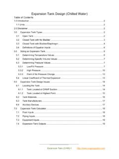
8 Similar to the base case, this method relies on cooling coils for DEHUMIDIFICATION but has the advantages of reduced coil load and free reheat. Wrap Around Coil with Cooling Coil This strategy employs a wrap around coil in addition to the cooling coil to make the process more energy efficient (see Figure 4). In this process, outside air, after passing through the enthalpy recovery wheel (1-2), goes over the first sensible coil, which reduces the air temperature (2-3); the air passes through the cooling coil (3-4) for DEHUMIDIFICATION and cooling. Then the air passes over a second sensible coil (4-5) to heat it to the desired supply air temperature. The first and second sensible coils are connected and transfer heat from air before the cooling coil to the air after the cooling coil. This helps reduce the cooling load on the primary cooling coil and provides free reheat.
9 Figure 3 Dual wheel: Schematic & Psychrometric chart Figure 4 Wrap-around coil: Schematic & Psychrometric chartTiered Cooling System (Direct Expansion + CHW) The level of DEHUMIDIFICATION through cooling and condensation is heavily dependent on the temperature of the cooling coil. In chilled water system design, the low coil temperatures required for this process dictate the design chilled water temperature (42-44 F). Designing and operating chillers at low temperatures increases the chiller lift and reduces the efficiency of the chiller. The tiered cooling approach decouples the latent ( DEHUMIDIFICATION ) and sensible cooling loads by using direct refrigerant expansion (DX) for latent cooling at the DOAS, and the chilled water system is designed and operated at a higher temperature (50-55 F), thus achieving building sensible cooling (60-70% of total cooling load) more efficiently compared to a low temperature chilled water system.
10 2018 ASHRAE ( ) and IBPSA-USA ( ). For personal use only. Additional reproduction, distribution, or transmission in either print or digital form is not permitted without ASHRAE or IBPSA-USA's prior written An advantage of DX DEHUMIDIFICATION , as compared to chilled water DEHUMIDIFICATION , is better humidity control. However, the disadvantage is lower efficiency. Figure 5 Psychrometric chart showing the cooling process for each strategy and THEIR corresponding cooling load. All STRATEGIES show cooling load reduction compared to the base case. (1-Base case, 2-Desiccant DEHUMIDIFICATION , 3-Dual wheel, 4-Wrap around coil) METHODOLOGY An air conditioning system s latent load is based on outdoor air (infiltration and ventilation air) and humidity gains from occupants and other internal processes. The other factor in latent load calculations is the indoor relative humidity set-point.