Transcription of Deinterleaving of Interfering Radars Signals in ...
1 Abstract In a dense modern electronic warfare environment, IFF/SSR systems receive a wide range of Signals from existing Radars . Among the most important tasks of such systems are recognition of Signals , extraction of work modes for each of the present objectives, separation of received Signals , their classification and identification of friend or foe. Because of the equality of the frequency of interrogation Signals , the similarity of pulse width in IFF/SSR Radars , and the lack of accuracy of the pulse amplitude as a proper criterion for classification, it is necessary to use a suitable algorithm for Deinterleaving and clustering of such Radars . By the present study, after proposing an optimized estimation of MRI mean value and devising a method for extracting Interfering Radars modes in received frame, the main lobes of the existing Radars in considered frame are selected based on choosing a proper threshold.
2 Then, using smoothing method, non-interfered parts of Radars are separated. In consequence, by determining MRI modulation type and Radars mode pattern from the non-interfered part, Deinterleaving of the Interfering Radars is done. Keywords Deinterleaving , IFF, Mode, MRI, SSR. I. INTRODUCTIONN telecommunications, identification Friend or Foe(IFF) is a cryptographic identification system designed for command and control. It is a system that enables military, and national civilian-located air traffic control (ATC) interrogation systems to distinguish friendly aircraft, vehicles, or forces, and to determine their bearing and range from the interrogator. IFF is still in use by both military and civilian aircraft. Modes 1, 2, 3, 4 and 5 are for military use only.
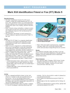
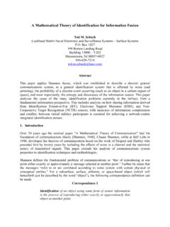
3 Modes 1, 2, 3 are composed of 3 pulses. These modes are identified by the interval of the pulses [1]-[2].Mode 4 is an identification mode with encrypted pulses. It has 4 pulses for synchronization and 32 pulses with encrypted information. As shown in fig. 1, the intervals between all pulses are equal to 2 microseconds and Pulse Width (PW) is microsecond, too. Younes Ahmadi, Electrical Engineering faculty Toosi University of Technology Tehran, Iran (phone: 98-21-84062214; e-mail: Kamal Mohamedpour, Electrical Engineering faculty Toosi University of Technology Tehran, Iran (phone: 98-21-84062214; e-mail: Moein Ahmadi, Electrical Engineering faculty Toosi University of Technology Tehran, Iran (phone: 98-21-84062214; e-mail: s 1.)))
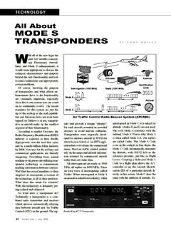
4 A general view of Mode 4 1P2P3 PModeT1 ModeT2 Figure 2. A general view of Modes 1, 2, 3, A, B, C, D Mode 5 is similar to Mode 4 and it is a crypto-secure Mode but enhanced with an Aircraft Unique PIN. Secondary surveillance radar (SSR) is a radar system used in ATC, which not only detects and measures the position of aircraft but also requests additional information from the aircraft itself such as its identity and altitude. SSR is based on the military identification friend or foe (IFF) technology, and the two systems are still compatible today. This radar contains five different work Modes (A, B, C, D, S). Fig. 2 and Table. I show a general view of Modes 1, 2, 3, A, B, C, D, and the characteristics of these Modes including radio frequency (RF), PW, and the interval between the pulses, respectively.
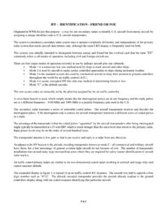
5 In Mode S the interval between P1and P2is equal to two microseconds and the respective PW is microsecond, also the intervals between P1and the pulse with information are and microseconds for short format and long format, respectively (as shown in fig. 3) [3]-[4].It should be noted that the frequencies of interrogation and reply Signals in IFF/SSR systems are 1030 and 1090 MHZ, respectively [5]. Regarding the shown values, it is clear that PW and RF cannot be Table I. the characteristics of Modes 1, 2, 3, A, B, C, D Deinterleaving of Interfering Radars Signals in identification Friend or Foe Systems Younes Ahmadi Kamal Mohamedpour Moein Ahmadi IRF)(MHZPW of 321,,PPP)(us)(1usTMode)( Telecommunications forum TELFOR 2010 Serbia, Belgrade, November 23-25, 3.
6 A general view of Mode S[4] considered as suitable criteria for Deinterleaving . Because of the fact that all IFF/SSR Radars make use of these Modes and the Interfering Radars adopt group pulse [6] with similar characteristics, it is a difficult and complex issue to separate Radars by use of the interval between the pulses. In this paper, minimum square error estimation of mode repetition interval (MRI) mean value is derived. Then, the method for extracting existing modes in frame and mathematical model for different types of MRI modulation along with their corresponding characteristics are presented. A method for separating non-interfered part of the main lobes of existing Radars in one frame and a method for determining MRI modulation type and work mode pattern of any radar are then presented.
7 Finally, the results of testing the proposed algorithm are shown in a simulation scenario presented in table 2. II. TIME OF ARRIVAL OF MODES Considering time of arrival (TOA) sequence measured by IFF/SSR system s receiver and in view of TOA of P1as representative of each mode, TOA sequence for a mode train in radar with N mode can be written as follows: NnzttnperfectnModen,..,2,1;=+= (1)where }{nzrepresents samples of zero mean white Gaussian noise with unit variance and2 is additive noise variance. The perfect TOA sequence,perfectnt,of a simple Mode train with Constant modulation can be written as follows: NnnDtperfectn,..,2,1;=+= (2) Dstands for intervals of Mode train and is the interval between the first received Mode by IFF/SSR system s receiver and the first Mode of the perfect Mode train.
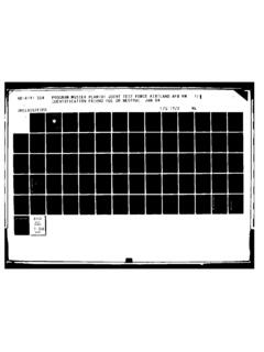
8 The minimum squared error can be used to estimate the interval. The square error is: 21)(),( ==NnperfectnModenttDMSE (3) By entering (2), into (3), then: 21))((),( + ==NnModennDtDMSE (4) Differentiate ),( DMSE with respect toDand ,and set the results equal to zero: =+ = =+ = ==NnModenNnModennDtDMSEnDtnDDMSE110))((0 ),(0))((0),( (5) Solving (5), Dis obtained and the estimation of Mode Repetition Interval (MRI) is as: )1()1(12])2)1(([1+ + == NNNtNnDModenNn(6) Conventionally, the mean value of MRI sequence, namelyaveMRI, has been estimated using the equation. 11 =NttMRIModeModenave(7) In fig. 4, the minimum square estimation error in (6), is compared with the error of common estimation (aveMRI). As shown in fig. 4, the estimation of (7), is more accurate and the proportion of mean MRI estimation per minimum square estimation errors increases as the number of Modes increases.
9 In the simulations of this figure, noise variance is considered to be 1 and Dis assumed to be 100. In [7] a matrix-based estimation for MRI mean value can be obtained using the following equation: Mean|)(|1 ModeModeTOATOATrNMRI(8) where ModeTOAN shows the number of Modes and Trdenotes the trace of a matrix which is defined as the summation of its diagonal elements. With respect to its thji),(element, ModeTOA matrix can be defined as follows: ModeTOAM odeiModejModeNjittjiTOA = ),(1|;|),((9) Equation (6) is a more accurate estimation than (8). It has also low computational complexity comparing with matrix-based estimation. IFF/SSR radar can change the interval between its modes in terms of different applications. MRI sequence can be expressed as: ,3,2;1= = (10) Enter (1), in (8), so: ,2,1;=+= (11) WherenDpresents interval between thnmode and thn)1( mode from the perfect modes train; }{nvis representative of samples of zero mean colored Gaussian noise with variance 2.
10 0500100015002000250030003500400045000246 8101214 Number of ModesPropertion of((MRIave-D)/(D1-D)Figure 4. Proportion of mean error per MSE error730IV. Mathematical Model for MRI Modulation IFF/SSR Radars can use different modes repetition patterns with respect to their application. The maximum length of a pattern is equal to the total number of its modes. The patterns are referred to as different types of MRI modulation. Fig. 6 shows different MRI modulations such as Constant, Sliding, Jittered, and Staggered. For separation of Radars with different MRI modulations, their mathematical model is first introduced. As shown in fig. 5, Constant MRI modulation has the simplest modulation in which the modes are repeated with the constant interval, D.)