Transcription of DELL OPTIPLEX XE - Dell United States
1 dell . OPTIPLEX XE. TECHNICAL GUIDEBOOK. INSIDE THE OPTIPLEX XE. OVERVIEW. Desktop Computer (DT) View 3. Desktop Back Panel Connectors 4. Desktop System Board 5. Small Form Factor Computer (SFF) View 6. Small Form Factor Back Panel Connectors 7. Small Form Factor System Board 8. MARKETING SYSTEM CONFIGURATIONS. Operating System, Chipset 9. Processor, Advanced System Manageability Modes, System Monitoring Options 10. Memory 11. Drives and Removable Storage 12-13. System Board Connectors, Graphics/Video Controller 13. External Ports/Connectors 14. Communications Integrated LAN, Wireless, Audio and Speakers, Keyboard and Mouse, Security 15. Security, Service and Support, Software, System Accessories 16. DETAILED ENGINEERING SPECIFICATIONS.
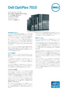
2 System Dimensions (Physical) 17. System Board Connector Maximum Allowable Dimensions 18. System Level Environmental and Operating Conditions 19. Power, Compliance 20. Audio 21. Communications 22-24. Graphics/Video Controller 24-26. Hard Drives 26-32. Optical Drive 33-34. BIOS Defaults 35. Chassis Enclosure and Ventilation Requirements 36. Acoustic Noise Emission Information 37-38. OPTIPLEX XE Technical Guidebook Page 2. DESKTOP COMPUTER (DT) VIEW. Front and Back View FRONT VIEW. 1 Drive activity light 4 Network activity light 2 7 External power button connector 2 Wi-Fi activity light 5 DVD drive bay 8 Diagnostic Lights (4). 3 Network activity light 1 6 USB connectors (2) 9 Power button, power light BACK VIEW. 10 Power supply diagnostic button 13 Padlock ring 16 Back panel connectors 11 Power supply diagnostic light 14 Security cable slot 17 Expansion card slots (4).
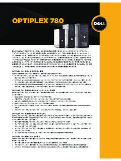
3 12 Cover release latch 15 Power cable connector OPTIPLEX XE Technical Guidebook Page 3. DT Back Panel Connectors BACK PANEL CONNECTORS. 1 Serial Connector 1 10 PS/2 Mouse Connector 2 Link Integrity Light 2 11 Line-Out Connector 3 Network Adapter Connector 2 12 Line-In/Mic Connector 4 Network Activity Light 2 13 PS/2 Keyboard Connector 5 Link Integrity Light 1 14 VGA Connector 6 Network Adapter Connector 1 15 24V Powered USB Connector (TruManage Capability). 7 Network Activity Light 1 16 USB Connectors (4). 8 Serial Connector 2 17 DisplayPort 9 Wi-Fi Connector OPTIPLEX XE Technical Guidebook Page 4. DT System Board 1 Processor power connector (12 VPOWER) 17 Serial Port Jumper (J3 & J4). 2 Processor connector (CPU) 18 Power connector (24V POWER).
4 3 Memory module connectors (DIMM_4) 19 Serial Port Jumper (J1 & J2). 4 Memory module connectors (DIMM_2) 20 PCI Express x16 card connector(SLOT1). 5 Memory module connectors (DIMM_3) 21 PCI card connectors (SLOT2). 6 Memory module connectors (DIMM_1) 22 PCI card connectors ( SLOT3). 7 Battery socket (BATTERY) 23 PCI Express x1 card connector(SLOT4). 8 Password jumper (PSWD) 24 Intruder connector (INTRUDER). 9 SATA drive connectors (SATA0) 25 RTC reset jumper (RTCRST). 10 SATA drive connectors (SATA1) 26 Internal buzzer (SPKR). 11 SATA drive connectors (SATA2) 27 Speaker connector (INT_SPKR). 12 Thermal sensor connector (rear) 28 Thermal Sensor connector (front). 13 Front-panel connector (FRONTPANEL) 29 Fan connector (FAN_HDD).
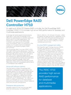
5 14 External Power USB connector 30 Connector for optional wireless card 15 Internal USB connector 31 Fan connector (FAN_CPU). 16 Power connector (POWER). OPTIPLEX XE Technical Guidebook Page 5. Small Form Factor (SFF) Computer View Front and Back View FRONT VIEW. 1 Drive activity light 4 Network activity light 2 7 External power button connector 2 Wi-Fi activity light 5 DVD drive bay 8 Diagnostic Lights (4). 3 Network activity light 6 USB connectors (2) 9 Power button, power light 1. BACK VIEW. 10 Power supply diagnostic button 13 Padlock ring 16 Back panel connectors 11 Power supply diagnostic light 14 Security cable slot 17 Expansion card slots (2). 12 Cover release latch 15 Power cable connector OPTIPLEX XE Technical Guidebook Page 6.
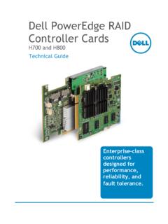
6 SFF Back Panel Connectors BACK PANEL CONNECTORS. 1 Serial Connector 1 10 PS/2 Mouse Connector 2 Link Integrity Light 2 11 Line-Out Connector 3 Network Adapter Connector 2 12 Line-In/Mic Connector 4 Network Activity Light 2 13 PS/2 Keyboard Connector 5 Link Integrity Light 1 14 VGA Connector 6 Network Adapter Connector 1 15 24V Powered USB Connector (TruManage Capability). 7 Network Activity Light 1 16 USB Connectors (4). 8 Serial Connector 2 17 DisplayPort 9 Wi-Fi Connector OPTIPLEX XE Technical Guidebook Page 7. SFF System Board 1 Processor power connector (12 VPOWER) 16 Power connector (POWER). 2 Processor connector (CPU) 17 Serial Port Jumper (J3 & J4). 3 Memory module connectors (DIMM_4) 18 Power connector (24V POWER).
7 4 Memory module connectors (DIMM_2) 19 Serial Port Jumper (J1 & J2). 5 Memory module connectors (DIMM_3) 20 PCI Express x16 card connector(SLOT1). 6 Memory module connectors (DIMM_1) 21 PCI card connectors (SLOT2) - half height 7 Battery socket (BATTERY) 22 Intruder connector (INTRUDER). 8 Password jumper (PSWD) 23 RTC reset jumper (RTCRST). 9 SATA drive connectors (SATA0) 24 Internal buzzer (SPKR). 10 SATA drive connectors (SATA1) 25 Fan connector (FAN_HDD). 11 SATA drive connectors (SATA2) 26 Speaker connector (INT_SPKR). 12 Thermal sensor connector (rear) 27 Thermal Sensor connector (front). 13 Front-panel connector (FRONTPANEL) 28 Fan connector (FAN_CPU). 14 External Power USB connector 29 Connector for optional wireless card 15 Internal USB connector OPTIPLEX XE Technical Guidebook Page 8.
8 Marketing System Configurations NOTE: Offerings may vary by region. For more information regarding the configuration of your computer, click Start Help and Support and select the option to view information about your computer. Operating System NOTE: One of the following Operating Systems will be preinstalled. DT SFF. Windows 7 operating system Microsoft Windows 7 Ultimate (32/64. bit). Windows 7 Professional (32/64 bit). Microsoft Windows 7 Home Premium (32-bit). Microsoft Windows 7 Home Basic(select countries). Windows Vista operating system Microsoft Windows Vista Business (32/64 bit) Microsoft Windows Vista . Home Basic Microsoft Windows Vista Business Downgrade via Windows 7 Professional Windows XP operating system Microsoft Windows XP Professional Downgrade via Windows 7 Ultimate or Professional Microsoft Windows XP Professional Downgrade via Windows Vista Business Microsoft Windows XP Home (China only).
9 Other Microsoft Windows Embedded POSR eady 2009. Ubuntu Linux (China only). FreeDOS for N-series OS Media Support X X. Chipset NOTE: The OPTIPLEX XE uses a Chipset from Intel's long lifecycle Embedded Roadmap DT SFF. Chipset Intel Q45 Express Chipset w/ICH10DO. Non-volatile memory on chipset BIOS Configuration SPI (Serial Peripheral Interface) 16 Mbit (2MB) located at SPI_FLASH on chipset NIC EEPROM 5761 8 Mbit, 57780 OTP. OPTIPLEX XE Technical Guidebook Page 9. Processor NOTES: The OPTIPLEX XE uses CPUs from Intel's long lifecycle Embedded Roadmap Processor numbers are not a measure of performance. Processor availability subject to change and may vary by region/country DT SFF. Intel Core 2 Duo and Pentium Dual Core Processors Intel Core 2 Duo E7400 , 3M, 1066 FSB X X.
10 Intel Pentium Dual-Core E5300 , 2M, 800 FSB X X. Intel Celeron Processors Intel Celeron 440 , 512K, 800 FSB X X. Advanced System Manageability Modes NOTE: Hardware management mode options allow you to select the right systems management feature support for your enterprise. dell 's innovative approach to scalable remote client management offers you a choice of built-in hardware management capabilities across platform offerings. The latest generation of Broadcom TruManage technology provides the capability to manage your install base of systems regardless of the power or O/S state of the system. This functionality allows IT to address many issues remotely rather than having to physically visit systems. The OPTIPLEX XE supports Broadcom TruManage technology which supports the following features: BIOS Management, asset reporting, remote troubleshooting and repair, power on for remote patching/updating.