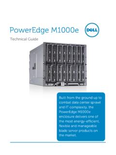
Transcription of Dell PowerEdge FN I/O Aggregator Installation Guide
1 Dell PowerEdge FN I/O AggregatorInstallation GuideNotes, Cautions, and WarningsNOTE: A NOTE indicates important information that helps you make better use of your : A CAUTION indicates either potential damage to hardware or loss of data and tells you how to avoid the : A WARNING indicates a potential for property damage, personal injury, or 2014 Dell Inc. All rights reserved. This product is protected by and international copyright and intellectual property laws. Dell and the Dell logo are trademarks of Dell Inc. in the United States and/or other jurisdictions. All other marks and names mentioned herein may be trademarks of their respective A01 Contents1 About this Unpack the Hardware You and Configuring the the Aggregator in a PowerEdge a Console a Switch the Switch MUX Technical Agency Federal Communications Commission (FCC) Department of Communication Union EMC Directive Conformance Community : VCCI Compliance for Class A Certification of Standards and Compliance Agency Compatibility (EMC).
2 21 Product Recycling and Technical Dell Networking Technical this GuideThis Guide provides site preparation recommendations and step-by-step procedures for rack mounting, installing and replacing pluggable modules, and connecting to a power you have completed the hardware Installation and power-up of the Dell PowerEdge FN I/O Aggregator , for software configuration information, refer to the Dell Networking Operating System (OS) Configuration Guide for the Dell PowerEdge FN I/O Aggregator and for command line interface (CLI) information, refer to the Dell Networking OS Command Line Reference Guide for the Dell PowerEdge FN I/O : To avoid electrostatic discharge (ESD) damage, wear grounding wrist straps when handling this : Only trained and qualified personnel can install this equipment.
3 Read this Guide before you install and power up this equipment. This equipment contains two power cords. Disconnect both power cords before : This equipment contains optical transceivers that comply with the limits of Class 1 laser : When no cable is connected, visible and invisible laser radiation may be emitted from the aperture of the optical transceiver ports. Avoid exposure to laser radiation and do not stare into open apertures. Information SymbolsThis book uses the following information symbols:NOTE: The Note icon signals important operational : The Caution icon signals information about situations that could result in equipment damage or loss of : The Warning icon signals information about hardware handling that could result in this Guide5 WARNING: The ESD Warning icon requires that you take electrostatic precautions when handling the PublicationsFor more information about the Dell PowerEdge FN I/O Aggregator , refer to the following documents.
4 Dell Networking OS Configuration Guide for the Dell PowerEdge FN I/O Aggregator Dell Networking OS Command Line Reference Guide for the Dell PowerEdge FN I/O Aggregator Dell Networking OS Release Notes for the Dell PowerEdge FN I/O AggregatorNOTE: For the most recent documentation and software, visit Dell Networking Technical Support (registration for access to some sections is required): this Guide2 IntroductionThis document provides basic information about the Dell PowerEdge FN I/O Aggregator , including how to install and perform the initial information about how to configure and monitor switch features, refer to the Dell Networking OS Configuration Guide for the Dell PowerEdge FN I/O Aggregator , which is available on the Dell Support website at Product DescriptionThe Aggregator is a multi layer, 12x10 Gigabit Ethernet switch that operates in a Dell PowerEdge FX2 server chassis, which can support up to eight servers and two Aggregator switches with four uplink interfaces Dell PowerEdge FX2 server chassis is managed by a single chassis management controller (CMC)
5 , which is similar to the CMC unit on the Dell PowerEdge M1000e and provides management connectivity to two I/O modules and the Integrated Dell Remote Access Controller (iDRAC) units of all eight the SwitchWhen unpacking each switch, make sure that the following items are included: One Dell PowerEdge FN I/O Aggregator One USB type A-to-DB-9 female cable Getting Started Guide Safety and Regulatory Information Warranty and Support Information Software License Agreement Unpacking StepsNOTE: Before unpacking the switch, inspect the container and immediately report any evidence of the container on a clean, flat surface and cut all straps securing the the container or remove the container remove the switch from the container and place it on a secure and clean all packing the product and accessories for the Switch4 Hardware OverviewThis section contains information about device characteristics and modular hardware configurations for the Dell PowerEdge FN I/O PanelAll fixed data ports (4 1/10G uplink ports) are on the I/O I/O panel includes: Four fixed data ports USB Console port USB Storage port Light emitting diodes (LEDs)Figure 1.
6 I/O Panel1 USB Console Port2 USB Storage Port3 Activity and Link Status LEDs4 Four fixed data PortsNOTE: The LED displays for system status are on both sides of the chassis. The fan and power status LEDs are on the Utility Overview9 Power SuppliesThe Dell PowerEdge FX2 server chassis supports two hot-swappable power supply units (PSUs).NOTE: You must install the PSUs at your are field-replaceable. To ensure power redundancy and adequate cooling, install two power supplies in the switch. When running with full redundancy (two PSUs installed and running), you can remove and replace a PSU while the other PSUs are running without disrupting Dell PowerEdge FX2 server chassis supports eight fan : You must install the fans at your NumberingWhen installed in a server enclosure, the Dell PowerEdge FN I/O Aggregator ports are numbered from 1 to 12.
7 Ports from 1 to 8 are internal server-facing ports. Ports from 9 to 12 are external ports numbered from the left to the right of the following three Aggregators are supported with the external interfaces on the front: FN 410S (4x10G SFP+) FN 410T (4x10G Base-T) FN 2210S (4x10G Combo ports with Ethernet and Fibre Channel)The properties of the Combo card are: Ports 9 and 10 are fibre channel (FC) type and support eight Gigabit FC, by default. Ports 11 and 12 are Ethernet type and support 10 Gigabit Ethernet, by default. You can convert ports 9 and 10 to Ethernet type by using the port mode configure a port, specify the slot (from 0 to 5; default: 0) and port number (from 1 to 12) in the interface port-type slot/port command, where slot is the unit number of the Aggregator displayed in the show system brief command.
8 For example:Dell(conf)# interface tengigabitethernet 0/4 System StatusYou can view the Aggregator status information in several ways, including LEDs and boot menu can also view status information through the show commands and with the simple network management protocol (SNMP).The Aggregator includes LED displays as shown in the following OverviewFigure 2. System LED Displays (I/O Panel)1 System Status LED2 System Power LEDThe following table lists the LED definitions for the 1. System LED DisplaysSystem LEDLED Color/DisplayDescriptionPower Green Off Power is being supplied to the switch. The switch does not have Blue Off Amber The switch is operating normally as a standalone switch or as a stack master.
9 The switch is not the stack master. A fault has occurred, or the switch is : The front-end ports also contain LEDs that provide information about the link status and traffic activity on a : When the ingress air temperature exceeds 60 C, the Status LED turns amber and a major alarm is 2. SFP+ and 10G BaseT Port LEDsLabelLED Color/DisplayDescriptionLink LED Off Solid green Solid amber The port is down. The port is up and can transmit traffic at maximum speed. A SFP+ or BaseT port can transmit at 10G. The port is up and is transmitting traffic at lower than maximum speed. A SFP+ or BaseT port is transmitting at LED Off Blinking green No traffic is being transmitted or received on the port. Traffic is being transmitted or received on the Overview115 InstallationThis switch Installation procedure assumes the Dell PowerEdge FX2 server chassis is installed correctly.
10 For complete instructions for Installation , refer to the Dell PowerEdge FX2 server chassis Installation Guide . Before You BeginBefore installing the switch, ensure that the chosen Installation location meets the following site requirements: Clearance There is adequate front and back clearance for operator access. Allow clearance for cabling, power connections, and ventilation. AC/DC power cord The cord reaches from the power outlet to the Utility-panel connector. Cabling The cabling is routed to avoid sources of electrical noise such as radio transmitters, broadcast amplifiers, power lines, and fluorescent lighting fixtures. Airflow The airflow around the switch and through the vents is unrestricted.


