Transcription of Dell PowerEdge R720 and R720xd Owner's Manual
1 Dell PowerEdge R720 and R720xdOwner's ManualRegulatory Model: E14S SeriesRegulatory Type: E14S001 Notes, Cautions, and WarningsNOTE: A NOTE indicates important information that helps you make better use of your : A CAUTION indicates either potential damage to hardware or loss of data and tells you how to avoid the : A WARNING indicates a potential for property damage, personal injury, or 2014 Dell Inc. All rights reserved. This product is protected by and international copyright and intellectual property laws. Dell and the Dell logo are trademarks of Dell Inc. in the United States and/or other jurisdictions. All other marks and names mentioned herein may be trademarks of their respective - 10 Rev. A07 Contents1 About Your Features And Panel Indicator Features And Indicator Indicator Information You May Using The System Setup and Boot The System Boot System To Error The System Setup Navigation Setup Setup Main BIOS Information settings Settings Settings Settings devices Communications Profile Settings Security And Setup Password A System And/Or Setup Or Changing An Existing System And/Or Setup Your System Password To Secure Your With A Setup Password The UEFI Boot The Boot Manager Navigation Manager Boot System Settings The iDRAC Settings The Thermal Installing System Bezel (Optional).
2 36 Removing The Front The Front And Closing The The The The The Cooling The Cooling Memory Module Installation memory Memory Memory A Inch Hard-Drive A Inch Hard-Drive A Inch Hard-Drive Blank (Back)..50 Installing A Inch Hard-Drive Blank (Back)..51 Removing A Inch Hard-Drive A Inch Hard-Drive A Hot-Swap Hard A Hot-Swap Hard A Hard Drive From A Hard-Drive A Hard Drive Into A Hard-Drive Drive (Optional)..54 Removing The Optical The Optical A Cooling A Cooling The Cooling-Fan The Cooling-Fan USB Memory Key (Optional)..58 Replacing The Internal USB Card The PCIe Card The PCIe Card And Closing The PCIe Card Holder Cover Lock The Top Cover Lock Retention The Cable Retention The Cable Retention Cards And Expansion-Card Card Installation An Expansion Card From The Expansion-Card Riser 2 Or An Expansion Card Into The Expansion-Card Riser 2 Or An Expansion Card From The Expansion-Card Riser An Expansion Card Into The Expansion-Card Riser Expansion-Card Expansion-Card Card Installation A GPU A GPU vFlash An SD vFlash The vFlash Media The vFlash Media Dual SD The Internal Dual SD The Internal Dual SD SD An Internal SD An Internal SD Storage Controller The Integrated Storage Controller The Integrated Storage Controller Daughter The Network
3 Daughter The Network Daughter A A Spare An AC Power An AC Power Instructions For A DC Power A DC Power A DC Power The Power Supply The Power Supply The System The Hard-Drive The Hard-Drive The Optional Hard-Drive Backplane (Back)..107 Installing The Optional Hard-Drive Backplane (Back)..108 Control Panel The Control Panel ( PowerEdge R720)..109 Installing The Control Panel ( PowerEdge R720)..110 Removing The Control Panel ( PowerEdge R720xd )..111 Installing The Control Panel ( PowerEdge R720xd )..112 Removing The I/O Panel ( PowerEdge R720xd )..112 Installing The I/O Panel ( PowerEdge R720xd )..113 System The System The System Troubleshooting Your First For You And Your System Startup External The Video A USB A Serial I/O A A Wet A Damaged The System Power Cooling Cooling System An Internal USB An SD An Optical A Tape Backup A Hard A Storage Expansion Using system Online Embedded System To Use The Embedded System The Embedded System Diagnostic Jumpers And Board Jumper Board A Forgotten Technical System LCD LCD Error Getting Your SystemTopics.
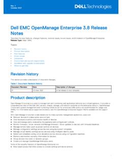
4 Front-Panel Features And Indicators LCD Panel Features Diagnostic Indicators Hard-Drive Indicator Patterns Back-Panel Features And Indicators NIC Indicator Codes Power Indicator Codes Other Information You May NeedFront-Panel Features And IndicatorsFigure 1. Front-Panel Features and Indicators ( Inch Chassis) PowerEdge R720 Figure 2. Front-Panel Features and Indicators ( Inch Chassis) PowerEdge R720 ItemIndicator, Button, or ConnectorIconDescription1 Power-on indicator, power buttonThe power-on indicator lights when the system power is on. The power button controls the power supply output to the Your SystemItemIndicator, Button, or ConnectorIconDescriptionNOTE: On ACPI-compliant operating systems, turning off the system using the power button causes the system to perform a graceful shutdown before power to the system is turned buttonUsed to troubleshoot software and device driver errors when running certain operating systems.
5 This button can be pressed using the end of a paper this button only if directed to do so by qualified support personnel or by the operating system's identification buttonThe identification buttons on the front and back panels can be used to locate a particular system within a rack. When one of these buttons is pressed, the LCD panel on the front and the system status indicator on the back flashes until one of the buttons is pressed to toggle the system ID on and the system stops responding during POST, press and hold the system ID button for more than five seconds to enter BIOS progress reset iDRAC (if not disabled in F2 iDRAC setup) press and hold the button for more than 15 connectorAllows you to connect a VGA display to the menu buttonsAllows you to navigate the control panel LCD tagA slide-out label panel which allows you to record system information such as Service Tag, NIC, MAC address and so on as per your panelDisplays system ID, status information, and system error messages.
6 The LCD lights blue during normal system operation. The LCD lights amber when the system needs attention, and the LCD panel displays an error code followed by descriptive : If the system is connected to a power source and an error is detected, the LCD lights amber regardless of whether the system is turned on or drive (optional)One optional SATA DVD-ROM drive or DVD+/-RW inch hard drive systemsUp to eight inch hot-swappable inch hard drive systemsUp to sixteen inch hot-swappable hard Your System9 ItemIndicator, Button, or ConnectorIconDescriptionNOTE: In systems supporting Dell PowerEdge Express Flash devices (PCIe SSDs), hard-drive slots 0 through 3 in hard-drive bay 2 support only PCIe SSDs. Hard-drive bay 3 does not support any hard drives and is installed with a hard-drive media card slotAllows you to insert a vFlash media connectors (2)Allows you to connect USB devices to the system.
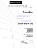
7 The ports are USB drive slot (optional)One optional inch tape backup 3. Front-Panel Features and Indicators ( Inch Chassis) PowerEdge R720xdFigure 4. Front-Panel Features and Indicators ( Inch Chassis) PowerEdge R720xdItemIndicator, Button, or ConnectorIconDescription1 Diagnostic indicatorsThe diagnostic indicators light up to display error identification buttonThe identification buttons on the front and back panels can be used to locate a particular system within a rack. When one of these buttons is pressed, the system status indicator on the back flashes until one of the buttons is pressed to toggle the system ID on and the system stops responding during POST, press and hold the system ID button for more than five seconds to enter BIOS progress reset the iDRAC (if not disabled in F2 iDRAC setup) press and hold the button for more than 15 Your SystemItemIndicator, Button, or ConnectorIconDescription3 Power-on indicator, power buttonThe power-on indicator lights when the system power is on.
8 The power button controls the power supply output to the : On ACPI-compliant operating systems, turning off the system using the power button causes the system to perform a graceful shutdown before power to the system is turned buttonUsed to troubleshoot software and device driver errors when running certain operating systems. This button can be pressed using the end of a paper this button only if directed to do so by qualified support personnel or by the operating system's inch hard drive systemsUp to twelve inch hot-swappable hard inch hard drive systemsUp to twenty-four inch hot-swappable hard connectorAllows you to connect a VGA display to the connectorAllows you to connect USB devices to the system. The port is USB tagA slide-out label panel which allows you to record system information such as Service Tag, NIC, MAC address, and so on as per your Panel FeaturesNOTE: The LCD panel is present only on PowerEdge system's LCD panel provides system information and status and error messages to indicate when the system is operating correctly or when the system needs attention.
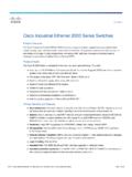
9 See System Error Messages for information about specific error codes. The LCD backlight lights blue during normal operating conditions and lights amber to indicate an error condition. The LCD backlight is off when the system is in standby mode and can be turned on by pressing either the Select, Left, or Right button on the LCD panel. The LCD backlight remains off if LCD messaging is turned off through the iDRAC utility, the LCD panel, or other 5. LCD Panel FeaturesAbout Your System11 ItemButtonDescription1 LeftMoves the cursor back in one-step the menu item highlighted by the the cursor forward in one-step message scrolling: Press once to increase scrolling speed Press again to stop Press again to return to default scrolling speed Press again to repeat the cycleHome ScreenThe Home screen displays user-configurable information about the system.
10 This screen is displayed during normal system operation when there are no status messages or errors. When the system is in standby mode, the LCD backlight turns off after five minutes of inactivity if there are no error messages. Press one of the three navigation buttons (Select, Left, or Right) to view the Home navigate to the Home screen from another menu, continue to select the up arrow until the Home icon is displayed, and then select the Home the Home screen, press the Select button to enter the main MenuNOTE: When you select an option in the Setup menu, you must confirm the option before proceeding to the next DHCP or Static IP to configure the network mode. If Static IP is selected, the available fields are IP, Subnet (Sub), and Gateway (Gtw). Select Setup DNS to enable DNS and to view domain addresses.