Transcription of DELL TM - clascsg.uconn.edu
1 technical GUIDEBOOK INSIDE THE optiplex 790 TM TM dell optiplex 790OV E R V I E W Mini Tower Computer (MT) View 3-4 Desktop Computer (DT) View 5-6 Small Form Factor Computer (SFF) View 7-8 Ultra Small Form Factor Computer (USFF) View 9-10 M A R K E T I NG S Y S T E M C O NF I G U R A T I O N S Operating System, Chipset 11 Processor 12 Memory 13 Drives and Removable Storage, System Expansion Slots 14-15 Graphics/Video Controller 16 External Ports/Connectors 16 Communications Network Adapter (NIC) 17 Audio and Speakers, Keyboard and Mouse 17 Security, Service and Support, Software 18 D E T A I L E D E N GI N E E R I N G S P E C I F I C A T I O N S System Dimensions (Physical)
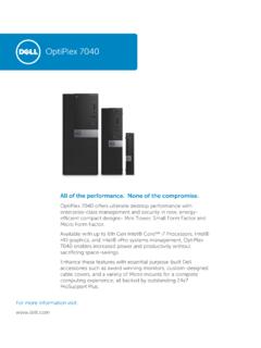
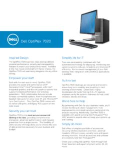
2 19 System Expansion Slots 19 System Level Environmental and Operating Conditions 20 Power 21-22 Audio 23 Communications 24-27 Graphics/Video Controller 28-29 Hard Drives 30-38 Optical Drive 39-40 BIOS Defaults 41 Chassis Enclosure and Ventilation Requirements 42 Acoustic Noise Emission Information 43-46 TABLE OF CONTENTS dell optiplex 790 technical GUIDEBOOK - V 3 FRONT VIEW 1 Power Button, Power Light 6 Optical Drive (optional) 2 Optical Drive Bay (optional) 7 Optical Drive Eject Button 3 Headphone Connector 8 USB Connectors (4) 4 Microphone Connector 9 Drive Activity Light 5 Diagnostic Lights (4) BACK VIEW 10 Power Supply Diagnostic Light 14 Expansion card slots(4) 11 Power Supply Diagnostic Button 15 Security cable slot 12 Power Connector 16 Padlock Ring 13 Back Panel Connectors BACK PANEL CONNECTORS 1 Mouse Connector 7 Keyboard Connector 2 Link Integrity Light 8 USB Connectors (6) 3 Network Connector 9 Display Port Connector 4 Network Activity Light 10 VGA Connector 5 Serial connector 11 Line-in/Microphone connector 6 Line-out Connector M I NI T OW ER C O M P UT ER ( MT )
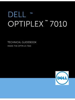
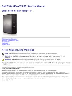
3 V I EW dell optiplex 790 technical GUIDEBOOK - V 4 M I NI T OW ER C O M P UT ER ( MT ) V I EW Number Name Number Name 1 Internal speaker connector(INT_SPKR) 13 PCI connector(SLOT3) 2 Front IO connector(FRONTPANEL) 14 PCI-e 4x connector(SLOT4) 3 Thermal sensor connector(THRM_2) 15 Intrusion switch connector(INTRUDER) 4 SATA 0 connector(SATA0) 16 System fan connector(FAN_HDD) 5 SATA 1 connector(SATA1) 17 P2 power connector(12V_PWRCONN) 6 SATA 2 connector(SATA2) 18 Processor connector(N/A) 7 SATA 3 connector(SATA3) 19 CPU fan connector(FAN_CPU) 8 Internal USB connector(INT_USB) 20 Memory connectors(DIMM1, DIMM2, DIMM3, DIMM4) 9 Buzzer(BEEP) 21 Power switch connector(PWR_SW) 10 LPC debug connector(LPC_DEBUG) 22 Battery connector(BATTERY) 11 PCI-e 16x connector(SLOT1) 23 P1 power connector(POWER) 12 PCI-e 1x connector(SLOT2) dell optiplex 790 technical GUIDEBOOK - V 5 FRONT VIEW 1 Optical Drive 5 Microphone Connector 2 Optical Drive Eject Button 6 Headphone Connector 3 Power Button, Power Light 7 Drive Activity Light 4 USB Connectors (4) 8 Diagnostic Lights (4) BACK VIEW 9 Padlock Ring 13 Expansion card slots(4)
4 10 Security cable slot 14 Power Supply Diagnostic Light 11 Power Connector 15 Power Supply Diagnostic Button 12 Back Panel Connectors BACK PANEL CONNECTORS 1 Mouse Connector 7 Keyboard Connector 2 Link Integrity Light 8 USB Connectors (6) 3 Network Connector 9 Display Port Connector 4 Network Activity Light 10 VGA Connector 5 Serial connector 11 Line-in/Microphone connector 6 Line-out Connector D ES KT O P C O MP U T ER (D T ) V I EW dell optiplex 790 technical GUIDEBOOK - V 6 D ES KT O P C O MP U T ER (D T ) V I EW Number Name Number Name 1 Internal speaker connector(INT_SPKR) 13 PCI connector(SLOT3) 2 Front IO connector(FRONTPANEL) 14 PCI-e 4x connector(SLOT4) 3 Thermal sensor connector(THRM_2) 15 Thermal sensor connector(THRM_1) 4 SATA 0 connector(SATA0) 16 System fan connector(FAN_HDD) 5 SATA 1 connector(SATA1) 17 P2 power connector(12V_PWRCONN) 6 SATA 2 connector(SATA2) 18 Processor connector(N/A) 7 Internal USB connector(INT_USB) 19 CPU fan connector(FAN_CPU) 8 LPC debug connector(LPC_DEBUG) 20 Memory connectors(DIMM1, DIMM2, DIMM3, DIMM4) 9 Intrusion switch connector (INTRUDER)
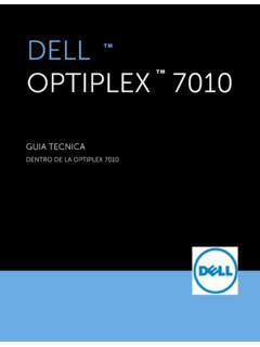
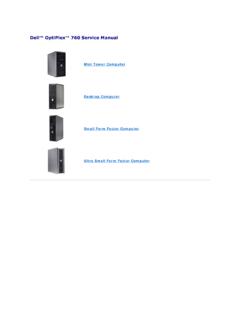
5 21 Power switch connector(PWR_SW) 10 Buzzer(BEEP) 22 Battery connector(BATTERY) 11 PCI-e 16x connector(SLOT1) 23 P1 power connector(POWER) 12 PCI-e 1x connector(SLOT2) dell optiplex 790 technical GUIDEBOOK - V 7 FRONT VIEW 1 Optical Drive 5 Microphone Connector 2 Optical Drive Eject Button 6 Headphone Connector 3 Power Button, Power Light 7 Diagnostic Lights (4) 4 USB Connectors (4) 8 Drive Activity Light BACK VIEW 9 Padlock Ring 13 Power Supply Diagnostic Light 10 Security cable slot 14 Back Panel Connectors 11 Power Connector 15 Expansion card slots(2) 12 Power Supply Diagnostic Button BACK PANEL CONNECTORS 1 Mouse Connector 7 Keyboard Connector 2 Serial connector 8 Display Port Connector 3 Link Integrity Light 9 VGA Connector 4 Network Connector 10 USB Connectors (6) 5 Network Activity Light 11 Line-in/Microphone connector 6 Line-out Connector S MA L L FOR M FA C T OR C OMP U TER ( S F F ) V IE W dell optiplex 790 technical GUIDEBOOK - V 8 S MA L L FOR M FA C T OR C OMP U TER ( S F F ) V IE W Number Name Number Name 1 P1 power connector(POWER) 12 LPC debug connector(LPC_DEBUG)
6 2 System fan connector(FAN_HDD) 13 Battery connector(BATTERY) 3 Internal speaker connector(INT_SPKR) 14 P2 power connector(12V_PWRCONN) 4 Buzzer(BEEP) 15 Processor connector(N/A) 5 PCI-e 4x connector(SLOT2) 16 CPU fan connector(FAN_CPU) 6 PCI-e 16x connector(SLOT1) 17 Power switch connector(PWR_SW) 7 SATA 2 connector(SATA2) 18 Memory connector(DIMM3) 8 SATA 1 connector(SATA1) 19 Memory connector(DIMM1) 9 SATA 0 connector(SATA0) 20 Memory connector(DIMM4) 10 Front IO connector(FRONTPANEL) 21 Memory connector(DIMM2) 11 Intrusion switch connector(INTRUDER) dell optiplex 790 technical GUIDEBOOK - V 9 U LTR A S MA L L F OR M FA CT OR C O MP U TER ( US F F ) V I EW FRONT VIEW 1 Optical Drive 5 Diagnostic Lights (4) 2 Optical Drive Eject Button 6 Headphone Connector 3 Power Button, Power Light 7 Microphone Connector 4 Drive Activity Light 8 USB Connectors (2) BACK VIEW 9 Wi-Fi Antenna (optional) 16 Line-in/ Microphone Connector 10 Network Activity Light 17 Display Port Connector 11 Captive Thumbscrew 18 VGA Connector 12 Padlock Ring 19 Serial Connector 13 Security Cable Slot 20 USB Connectors (5)
7 14 Power Connector 21 Network Connector 15 Line-Out Connector 22 Link Integrity Light dell optiplex 790 technical GUIDEBOOK - V 10 S MA L L FOR M FA C T OR C OMP U TER ( U S F F ) V IE W Number Name Number Name 1 Front panel connector(FRONTPANEL) 10 SATA 1 connector(SATA_1) 2 Memory connector(DIMM_2) 11 SATA 0 connector(SATA_0) 3 Memory connector(DIMM_1) 12 P1 power connector(POWER1) 4 CPU fan connector(FAN_CPU) 13 HDD-ODD power connector (HDD_ODD_POWER) 5 Internal speaker connector(INT_SPKR) 14 Intrusion switch connector(INTRUDER) 6 Buzzer(BEEP) 15 LPC debug connector(LPC_DEBUG) 7 Front IO connector(F_USB_AUDIO) 16 P2 power connector(12V_PWRCONN) 8 System fan connector(FAN_HDD) 17 Processor connector(N/A) 9 Mini-PCI socket(PCIE_MINICARD) 18 Battery connector(BATTERY) dell optiplex 790 technical GUIDEBOOK - V 11 MARKETING SYSTEM CONFIGURATIONS N O T E : O f f e r i n g s m a y v a r y b y c o u n t r y.
8 F o r m o r e i n f o r m a t i o n r e g a r d i n g t h e c o n f i g u r a t i o n o f y o u r c o m p u t e r , c l i c k S t a r t > H e l p a n d S u p p o r t a n d s e l e c t t h e o p t i o n t o v i e w i n f o r m a t i o n a b o u t y o u r c o m p u t e r . OP ER A TI N G SY S TE M MT DT SFF USFF Windows 7 operating system Microsoft Windows 7 Home Basic (32 and 64 bit) (select countries), Microsoft Windows 7 Home Basic SP1 (32 and 64 bit) (select coun-tries), Microsoft Windows 7 Home Premium (32 and 64 bit), Microsoft Windows 7 Professional (32 and 64 bit), Microsoft Windows 7 Ultimate (32 and 64 bit), Microsoft Windows 7 Starter SP1(32 bits), Microsoft Windows 7 Starter SP1 w/MUI (32 bits) Windows Vista operating system Windows Vista Home Basic SP2 (32 bits), Windows Vista Business SP2 (32 and 64 bit)
9 , Windows Vista Ultimate SP2 (32 bit) Windows XP operating system Basic Driver support only via Other FreeDOS for (N-series), Ubuntu Linux version (China only) OS Media Support Optional C H IP SE T MT DT SFF USFF Chipset Intel Q65 Express Chipset Non-volatile memory on chipset BIOS Configuration SPI (Serial Peripheral Interface) 64 Mbit (8MB) and 16 Mbit(2MB)located at SPI_FLASH on chipset TPM Security Device (Trusted Platform Module)1 18KB located at on chipset Non-TPM Available in select countries NIC EEPROM LOM configuration contained within SPI_FLASH no dedicated LOM EEPROM dell optiplex 790 technical GUIDEBOOK - V 12 PR O C E SS