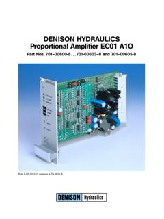
Transcription of DENISON HYDRAULICS Proportional Amplifier EC01 …
1 41. 53. 0.. 20mACommandSignal .. + + 0.. 0.. 10 VCommandSignal .. 5 CustomisedCommandSignal .. CommandValueFromAnExternalSignalSource .. DITHERFREQUENCY250Hz .. Maximum Current 3000 MaximumCurrent1600mA .. 86. 98. 99. JUMPERJP1 JUMPERJP4,JP5,JP6,JP7, 109. 1010. TRIMMING IMAXS etting .. 1111. 1112. 1213. 1314. 1315. 1416. CONNECTIONDIAGRAM(Example).. 1417. For4DP03 16 MODEL CODE, REFERENCE TABLE3 REFERENCE TABLEF actory settingDitherCurrentSeriesSol.
2 Order lnomlmin4RP0112 V 701-00614-8 250 Hz 150 mA2200 mA 0 mA4DP03E4DP06E12 V 701-00610-8 150 Hz 150 mA2200 mA 0 mAMODEL CODEM odel Number:EC01 A2 OSeriesA = Analogue version2 = for valves with 2 solenoidsO = Open loopDESCRIPTION, FEATURES, SPECIFICATION4 DESCRIPTIONThe Proportional Amplifier EC01 A2O has been developed to control severalDENISON hydraulic Proportional valves, which operate with two (2) requirements of thevalves,forexample nominal current, selected on the Proportional Amplifier by making the appropriate DIP factory settings are shown on page VDC supplyxreverse polarity supply voltage protectionxsolenoid output short circuit protectedxan external signal can start and stop the Proportional Amplifier (Stop-function)
3 Xan external signal can switch the ramp function on and offxlinearand,overa wide range,customeradjustable ramp up and ramp down timexdither amplitude adjustablexthree different dither frequencies selectable over DIP switch settingsxall industry standard command signals can be connectedxDIN 41612 connector type F (48 pin B-D-Z)xfulfils all the requirements of EMV and is CE certifiedSPECIFICATIONxDimensionsEuro card format 160 x 100 mmxFront plate dimensions 3U / 8HP (128. 5x mm)xWeightapprox. 250 gxConnectorDIN 41612, type F, 48 pinxSupply voltage24 VDC nominalxVoltage range20..32 VDC (battery or AC voltage,rectified and smoothed, ripple<5%)xCurrentapprox.
4 200 mA (+ solenoid current)xReference voltages 1 5V ( 5%) 50mA 10 V ( ) 10 mAxFive InputsCommand signal must be positive! 10 V3. Voltagecustomised selectable, R83=20 k /V(see layout diagram page 13)4. Current0.. 20 mA5. Current+ 4..+ 20 mAxOutput voltage24 V PWM for the solenoidxOutput currentlMAXapprox. 2700 mAxRange of adjustments: ( 20%) ( 20%)xDither mAxDither frequency100 Hz, 150 Hz, 250 Hz(selectable by DIP switch,see layout diagram page 13)xStorage temperature +125hCxOperating temperature +70hCFUNCTIONAL DESCRIPTION51. SUPPLY VOLTAGEThe Proportional Amplifier requires an external DC power supply. A diode on theinput protects the board against a powersupplyconnected with the wrong the Amplifier is a DC/DC converter the current consumption is less thanthe solenoid amplifiers can be connected to one power supply,which then has to meetthe following requirement:PMAX=nxP1(P1= requirement for one board, n = number of boards connected in parallel).
5 The DC voltage must be between 20 and 32 VDC. When the Amplifier is used tocontrol a valve with a 24 V solenoid then a voltage supply at the top end of thetolerance band (at least>26 V) is recommended. This is to ensure that thesolenoid has sufficient current at higher =+VSupplyB/D30 = 0 VSupplyZ2, Z32 = Earth (necessary for EMV)There is a current compensating coil in the supply line, with the result that the 0 Vline of the supply voltage is not identical with the ground potential of the this reason no connection may be made between the 0 V line of the supplyvoltage and the analogue ground of the Amplifier !2. REFERENCE VOLTAGESThe reference voltages 1 5 Vand 10 V(stabilised) are generated bya switchedmode DC/DC converter on the + 1 5 Vunstabilised approx.
6 50 mAB4= 1 5 Vunstabilised approx. 50 mAD2= + 10 Vstabilisedapprox. 10 mAD4= 10 Vstabilisedapprox. 10 mAThe reference voltages are used additionallyto powerexternal command potentio-meters, transducers or external electronic components for example 5-channelcommand the amplifierhas a stabilised 24 VDC supplyfortransducers,positionswitches , D32 = + 24 Vstabilisedapprox. 80 mAB6= GNDFUNCTIONAL DESCRIPTION63. COMMAND INPUTFive different current and voltage signals can be connected to the proportionalamplifier. This accommodates all the industry standard input com-mand input is set up as a differential forthe different input voltages and compensation forthe different inputcurrents is made by setting the DIP switches and jumpers (JP4 and JP5) on themain board(see page 13)
7 Is essential that the correct jumper and DIP switch settings are the jumper and/or DIP switch settings are incorrect then the Amplifier will not beable to generate the correct output current corresponding to the command = positive command voltageB12 = negative command COMMAND INPUT WITHDIFFERENTIAL INPUT FUNCTIONB ecause a differential Amplifier can only work correctly when, for the input andfeedback resistances, particular resistance combinations are selected (SW2 ),this amplifiercan onlybe used as a differential input amplifierwhen it is setup for a 10 V input diagram to the left shows the settings for a 10 V input signal with differentialinput potential on pin D12 must be more positive than the signal on B12 and thepotential difference between D12 and B12 must not exceed 10 JP4 and JP5 must be switches SW2/2 & SW2/4 must be clsed (ON).
8 COMMAND INPUT WITHOUTDIFFERENTIAL INPUT 0.. 20 mA COMMAND SIGNALJ umper JP5 mustbeclosedDIP switch SW2/6 must be closed (ON)!An input signal current of 0..+ 20 mA generates an output current of 0.. lMAXA respectively 0.. 20 mA generates an output current of 0.. input impedance is 100 . +4..+ 20 mA COMMAND SIGNALJ umper JP4 mustbeclosedDIP switch SW2/5, SW2/7 and SW2/8 must be closed (ON)!An input signal current of +4..+12 mA generates an output current of +12 mA ..+20 mA generates an output current of 0.. input impedance is 100 . 0.. 5 VCOMMANDSIGNALJ umper JP4 and Jumper JP5 must be openDIP switch SW2/3 must be closed (ON)!An input signal voltage of 0.
9 + 5V generates an output current of 0.. lMAXAand an input signal voltage of 0.. 5V generates an output current of 0.. command signal is normally used in conjunction with processor input impedance is 100 k .SW2SW2SW2 FUNCTIONAL DESCRIPTION7 COMMAND INPUT WITHOUTDIFFERENTIAL INPUT FUNCTION(continuation) 0.. 10 V COMMAND SIGNALJ umper JP4 and Jumper JP5 must be openDIP switch SW2/4 must be closed (ON)!An input signal voltage of 0..+ 10 V generates an output current of 0.. lMAXAand an input signal voltage of 0.. 10 Vgenerates an output current of 0.. command signal is normallyusedwhen an external command signal potentio-meter is also the description below:Command from external potentiometer (see ) or external signal source ( ).
10 The input impedance is 200 k . CUSTOMISED COMMAND SIGNALJ umper JP4 and Jumper JP5 must be openDIP switch SW2/1 must be closed (ON)!If a command signalvoltage is usedwhich doesnotcorrespondtoanyoftheabovevalues (for example 0.. 1 5V corresponding to 0.. 100% command signal)the appropriate DIPswitch has to be correspondinglyset and the resistorR83 (seepage 13) has to be calculated according to the maximum voltage level and fitted tothe value of the resistance is calculated as follows:R83 = VINx20k /VExample:Command signal 0.. 1 = 1 5V x 20 k /V = 300 k .The existing resistormust be then replacedwith a resistorhaving thevalue calcula-ted as input impedance is equal the new value of COMMAND VALUE FROM AN EXTERNAL POTENTIOMETERAs standard a 10 k command potentiometer (minimum k ) should be is then connected to +10 Vamplifierreference voltage (pin D2) and the 10 V(pin D4).