Transcription of DENSITY, In-Place Balloon Method - Alberta
1 ScopeATT-8/96 density , In-Place Balloon Method describes the procedure for using the Balloon Method density equipmentin the determination of In-Place field densities of fine grained soils, sand-base cementstabilized mixtures, asphalt or aggregate contaminated subgrades and granular or Volutester and accessory equipmentSieves: 20 000 Fm and 5 000 Fmpaint brushmixing spoonpicktablespoondrying pansgarden trowelwash basinsquare-nosed shovelchiselplastic jars and lidshammerData Sheet: Field density Test, MAT the Volumeasure or Volutester as directed in the applicablemanufacturers equipment the pressure gauge as directed in the Supplement section of thistest Method (ATT-8S).
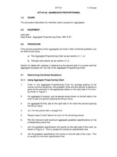
2 NOTE:The calibration is required at the start of the job, whenever thecalibration is in doubt or after the Balloon is the Final Pressure Reading from the last pressure gauge calibrationand record it in line "H". and tare a density jar including the lid. Record the jar number and thetare weight in line "P" of the data sheet as shown in Figure data sheet has 5 vertical columns for recording 5 tests per sheet. Whenmore than one test will be performed in the field, label and tare the requirednumber of plastic density jars and record the weights and numbers of thecontainers in line "P", one per vertical TEST HOLE VOLUMES(BASED ON MAXIMUM PARTICLE SIZE)MAXIMUMPARTICLESIZE (Fm)MINIMUMTEST HOLEVOLUME (cm)
3 35 00010 00012 50016 00020 00025 00040 0001 1501 3501 4501 6001 7501 9503 050 TABLE Volume of of HoleIf a fine grained soil sample or a sand-base CSBC sample has less than 7% of thetotal sample weight retained on the 5 000 Fm sieve, the volume of the test hole mustbe at least 1150 cm. When testing contaminated subgrade and base courses, use3 Table 1 to determine the volume of the density hole, according to the topsize of theaggregate being the test location andrecord the station, location anddepth below grade (or basecourse lift) and date in theappropriate lines of theheading portion of the datasheet, in the columncorresponding to the numberof the density jar to be used forthe the square nosed shoveland the garden trowel toremove soil until arepresentative moisturecontent is reached from anarea larger than the densityplate.
4 Typically a 50 mmdepth should be the surface with the square-nosed the density plate on the surface, press down and slide the the plate and trim the high spots with the garden steps 4 and 5 until the plate sits level and flat on the prepared is very important at the point where the soil meets the edges of the holein the density the Volumeasure or Volutester in the recess of the density plate andsecure it in place by tightening the two clamping devices. Mark the densityplate and base plate so that the two can be realigned in the same positionwhen taking the final the air release valve and insert the pump in the pressure the instrument snugly on the surface with one hand, and pump with theother until a pressure dial reading of is the air release valve.
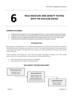
5 When the water level is stationary, lower your eyeparallel to the surface of the water. Read the bottom of the meniscus andrecord the Initial Scale Reading at Pressure in line "0".MAT 6-23 Volume of Hole (cont'd)FIELD density TESTSPROJECT 12:04 DISTRICT RED DEERPROJECT MANAGER I. KEENCONTRACT OF WORK GRADINGCONTRACTOR R. ROADSSITE LOCATION AND VISUAL DESCRIPTIONSTATION10+ m BELOW GRADE (RANGE) Method SOILS CLASSIFICATIONCIESTIMATED moisture content %OPTIMUMESTIMATED PERCENT COMPACTION%100+VOLUME OF HOLE (SAND Method )AWEIGHT OF SAND + CONTAINER BEFORE TESTgBWEIGHT OF SAND + CONTAINER AFTER TESTgCWEIGHT OF SAND IN FUNNEL AND HOLE OF density PANgDWEIGHT OF SAND USEDA - B - CgEUNIT WEIGHT OF CALIBRATED SANDg /cm3 FVOLUME OF HOLED / Ecm3 VOLUME OF HOLE (BALLON Method )GINITIAL SCALE READING AT PRESSUREcm390 HFINAL PRESSURE READING (FROM GAUGE CALIBRATION)
6 SCALE READINGcm31305 JFINAL ACTUAL READING (CYLINDER CALIBRATION CHART)cm31278 KINITIAL ACTUAL READING (CYLINDER CALIBRATION CHART)cm383 LVOLUME OF HOLEJ - Kcm31195 WET DENSITYMWEIGHT OF WET soil + ROCKS + OF ROCKS FROM OF WET soil + CONTAINERM - OF CONTAINER( ) OF WET SOILO - OF ROCKS FROM HOLEN / VOLUMEF - R or L - DENSITY1000 Q / S or 1000 Q / content AND DRY DENSITYUWEIGHT OF WET soil + OF DRY soil + OF PAN( ) OF WATERU - OF DRY SOILV - CONTENT100 X / Y% DENSITY100 T / (100 + Z) density TO MAXIMUM DRY density CORRELATIONBBMOISTURE- density RELATION CURVE NUMBER4 CCOPTIMUM moisture content % DRY DENSITYkg/m31679 EEPERCENT COMPACTION100 AA / DD% AND CONSTRUCTION EQUIPMENTSITE 1- DARK BROWN SANDY CLAY; MATERIAL FROM #5 m SHEEPSFOOT, 2-BLADES, 1-CAT & SCRAPERSITE 2 SITE 3 SITE 4 SITE 5 TECHNOLOGIST B.
7 GOODFIGURE Volume of Hole (cont'd)NOTE:Always read the water level the same way each time, that is, thebottom of the the pump and insert it in the vacuum the air release valve; pump the Balloon up into the graduated cylinderand close the air release the clamping devices and turn them out of the the Volumeasure or Volutester from the density plate. Leave thedensity plate in the excavating utensils to dig the density hole as follows:a)Use the trowel or chisel and hammer to shape a circle approximately6 mm inside the density plate opening. Hold the trowel or chiselvertically.
8 Where rocks are firmly seated, they may have to be )Use the trowel or chisel and mixing spoon to loosen the soil , workingoutward and upward form the middle of the circle to the edge shapedin (a).c)Use the mixing spoon to transfer the loosened soil and rocks into theempty labelled jar, taking care not to lose any material. Position thejar over the density plate when transferring soil , so that spilledmaterial will fall on the plate and can be ) place the lid on the density jar between transfers to prevent moistureloss through )Use the paint brush to brush material on the density plate into thehole and brush the sides of the hole to remove loosened material tothe )Repeat steps (b) to (e) until the walls of the excavation are relativelysmooth and the volume of the hole meets the minimum required sizeshown in Table.
9 Never pry the digging tools against the edge of the will cause the sides of the hole to distort, giving anerroneous the Volumeasure or Volutester in the recess on the density plate andsecure it in place by tightening the two clamp devices. The mark on thedensity plate should match with the line on the base the pump in the pressure position and open the air release the Balloon to fall into the hole until the water level is (cm3)'FinalActualReading&InitialActualRe adingVolume(cm3)'Volume(ft3) 28317cm3 Soils down firmly on the top of the instrument.
10 Begin until the pressure dial reading reaches the value recorded as FinalPressure Reading (line "H"). the air release valve and when the water level remains stationary,lower your eye parallel to the surface of the water. Read the bottom of themeniscus and record as Final Scale Reading (line "I"). the pump, open the valve and pump the Balloon up into thegraduated the clamping devices and remove the apparatus from the all the testing equipment in the equipment the Final Scale Reading (line "I") and the Cylinder Calibration Chart toobtain the Final Actual Reading (line "J").