Transcription of DEPARTMENT OF DEFENSE INTERFACE …
1 AMSC N/A FSC 2920 METRIC MIL-STD-1275D 29 August 2006 SUPERSEDING MIL-STD-1275C 23 June 2006 DEPARTMENT OF DEFENSE INTERFACE STANDARD CHARACTERISTICS OF 28 VOLT DC ELECTRICAL SYSTEMS IN MILITARY VEHICLES MIL-STD-1275D ii FOREWORD 1. This standard is approved for use by all departments and agencies of the DEPARTMENT of DEFENSE (DOD). 2. The intent of this document is to provide standard limiting voltage characteristics for 28-volt direct current electric circuits on military ground platforms and electrical devices under test. 3. The authority shall designate responsibility for establishing appropriate characteristics of components powered from sources other than 28 VDC within the vehicle system. 4. Comments, suggestions, or questions on this document should be addressed to Tank-automotive and Armaments Command, 6501 E.
2 11 Mile Road, Warren, MI 48397-5000 or emailed to Since contact information can change, you may want to verify the currency of this address information using the ASSIST online database at MIL-STD-1275D iii CONTENTS PARAGRAPH PAGE FOREWORD .. ii 1. SCOPE .. 1 1 2. APPLICABLE DOCUMENTS .. 1 General .. 1 Government documents .. 1 Specifications, standards , and handbooks .. 1 Non-Government 1 Specifications, standards , and handbooks .. 1 Order of 2 3. DEFINITIONS .. 2 General .. 2 Vehicle power supply system .. 2 2 2 3 3 Recovery time .. 4 Ripple .. 4 Starting disturbances .. 5 Electrical Device Under Test (EDUT).. 5 Rise 5 Fall 5 4. GENERAL REQUIREMENTS.
3 6 Temperature conditions .. 6 Circuit characteristics point of 6 EDUT compatibility .. 6 Polarity .. 6 Load 6 Battery 6 MIL-STD-1275D iv 5. DETAILED REQUIREMENTS .. 6 Military ground platform electrical system requirements.. 6 Electromagnetic 6 Starting 7 Starting 7 Initial engagement 7 Cranking 7 Normal operating 7 Steady-state 7 7 8 9 Generator-only 9 Steady-state 9 9 10 11 Compatibility of power supply system and utilization 11 Test methods .. 11 Vehicle electrical system.. 12 Vehicle 12 General.. 12 Voltage spikes exported from 13 Voltage spikes imported into 15 Voltage surges imported into .. 16 Ripple voltage imported into .. 16 6. 17 Intended 17 Subject term (key word) 17 International 17 Changes from previous 17 MIL-STD-1275D v FIGURES PAGE 1.
4 Illustrative .. 3 2. Illustrative Surge with Recovery Time .. 4 3. General View of Ripple.. 4 4. Starting Disturbances .. 5 5. Envelope of Surges in Normal Operating Mode for 28 VDC 8 6. Envelope of Spikes in Normal Operating Mode for 28 VDC 9 7. Envelope of Surges in Generator-only Mode for 28 VDC 10 8. Envelope of Spikes in Generator-only Mode for 28 VDC 11 9. Exported Spike Test 13 10. Exported Spike Test Circuit (EDUT With Remote Switch).. 14 11. Imported Spike Test 14 12. Imported Surge Test Circuit for 28 VDC 15 MIL-STD-1275D 1 1. SCOPE Scope. This standard covers the limits of steady state and transient voltage characteristics 28 VDC electrical power systems for military ground vehicles. 2. APPLICABLE DOCUMENTS General. The documents listed in this section are specified in sections 3, 4 and 5 of this standard. This section does not include documents cited in other sections of this standard or recommended for additional information or as examples.
5 While every effort has been made to ensure the completeness of this list, document users are cautioned that they must meet all specified requirement documents cited in sections 3, 4 and 5 of this standard, whether or not they are listed. Government documents. Specifications, standards , and handbooks. The following specifications, standards , and handbooks form a part of this document to the extent specified herein. Unless otherwise specified, the issues of these documents are those listed in the issue of the DEPARTMENT of DEFENSE Index of Specifications and standards (DoDISS) and supplement thereto, cited in the solicitation. DEPARTMENT of DEFENSE MIL-STD-461 Requirements for the Control of Electromagnetic Interference Characteristics of Subsystems and Equipment (Copies of the above documents are available online at or or from the Standardization Document Order Desk, 700 Robbins Avenue, Building 4D, Philadelphia, PA 19111-5094).
6 Non-Government Documents. The following documents form a part of this document to the extent specified herein. Unless otherwise specified, the issues of documents are those cited in the solicitation or contract. Specifications, standards , and handbooks. MIL-STD-1275D 2 Society of Automotive Engineers (SAE) SAE J1113-2 Immunity to Conducted, 30 Hz to 250 kHz, Power Leads SAE J1113-11 Immunity to Conducted Transients on Power Leads SAE J1113-13 Electromagnetic Compatibility Measurements Procedure for Vehicle Components Part 13: Immunity to Electrostatic Discharge SAE J1113-42 Conducted Transient Emissions (Copies of the above documents are available from or from Society of Automotive Engineers, Inc. 400 Commonwealth Drive, Warrendale, PA 15096-0001). Order of precedence. In the event of a conflict between the text of this document and the references cited herein, the text of this document takes precedence.
7 Nothing in this document, however, supersedes applicable laws and regulations unless a specific exemption has been obtained. 3. DEFINITIONS General. For the purposes of this standard, the following definitions may apply. Vehicle power supply system. The DC voltage and current generating equipment, storage batteries, and distribution equipment normally fitted to the vehicle comprise the power supply system. Power is supplied from this system to the utilization equipment or electrical device under test. Transients. Transients are the changing conditions of a characteristic. These usually go beyond the steady-state limits, return to and remain within the steady-state limits within a specified time. The transient may take the form of either a surge or a spike. The elements of transient waveform characteristics are identified in paragraph and Figure A1 of SAE J1113-42. Surge. A surge is a variation from the controlled steady-state level of a characteristic, resulting from the inherent regulation of the electric power supply system and remedial action by the regulator, except for battery only operation.
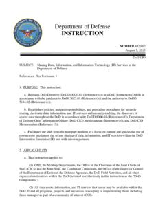
8 Surges may also occur due to the application of loads in the battery only condition. Surges are transients with duration greater than 1 ms and have a recovery time limitation. MIL-STD-1275D 3 Spike. A spike is a high frequency oscillatory variation from the controlled steady-state level of a characteristic. It results from very high frequency currents of complex waveforms produced when reactive loads are switched. An example of a spike waveform is shown in Figure 1. An individual spike generally has an interval lasting less than 50 microseconds ( s) but may take up to one millisecond (ms) to decay to the steady-state level. Vpeak0 VDCtrise FIGURE 1. Illustrative Spike. Steady-state. The condition in which circuit values remain essentially constant, occurring after all initial transients or fluctuating conditions have subsided. It is also definitive of the condition where, during normal system operation, only inherent or natural changes occur; ( , no malfunctions occur and no unanticipated changes are made to any part of the system).
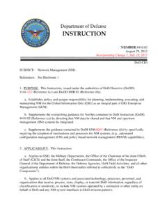
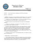
9 MIL-STD-1275D 4 Recovery time. The interval between the time a characteristic deviates from the steady-state limits and the time it returns and remains within the same range (see Figure 2). FIGURE 2. Illustrative Surge with Recovery Time. Ripple. The regular and/or irregular variations of voltage about a fixed DC voltage level during steady-state operation of a DC system. The upper and lower limits of the oscillations are called Upper Peak of Ripple Voltage and Lower Peak of Ripple Voltage, respectively (see Figure 3). FIGURE 3. General View of Ripple. MIL-STD-1275D 5 Starting disturbances. These are undervoltage variations from the steady-state level and are caused by engine starter engagement and cranking. A typical profile showing Initial Engagement Surge (IES) and Cranking Level is given in Figure 4. The duration of the initial engagement surge is measured from the instant at which it departs from the steady-state value to the instant at which it reaches and remains at the cranking level.
10 The cranking level may last no more than 30 seconds in length and there may be a minimum delay of 2 minutes in between cranking sets. During the initial engagement surge, the voltage may not fall below 6 VDC and the duration may not exceed 1 second. The steady voltage during cranking may not fall below 16 VDC (no more than three cranking attempts of 30 seconds each with 2 minute cranking level pauses between attempts). FIGURE 4. Starting Disturbances. Electrical Device Under Test (EDUT). The electronic device, equipment, or system utilized for testing and evaluation. It is also referred to as utilization equipment. Rise Time. The rise time is the difference between the time when the signal or voltage transient crosses a low threshold to the time when the signal or voltage transient crosses the high threshold. Fall Time. The fall time is the difference between the time when the signal or voltage transient crosses a high threshold to the time when the signal or voltage transient crosses the low threshold.