Transcription of Deploying a Fiber Optic Physical Infrastructure within a ...
1 Deploying a Fiber Optic Physical Infrastructure within a Converged Plantwide Ethernet ArchitectureApplication GuideJanuary 2018 Document Reference Number: ENET-TD003C-EN-P 1 Fiber Optic Infrastructure Application GuideENET-TD003C-EN-PDeploying a Fiber Optic Physical Infrastructure within a Converged Plantwide Ethernet ArchitectureIntroductionConverged Plantwide Ethernet (CPwE) is the underlying architecture that provides standard network services for control and information disciplines, devices, and equipment found in modern industrial automation and control system (IACS) applications.
2 CPwE is a collection of tested and validated architectures that are developed by subject matter authorities at Cisco, Panduit1, and Rockwell Automation that follow the Cisco Validated Design (CVD) program. The content of CPwE, which is relevant to both Operational Technology (OT) and Informational Technology (IT) disciplines, consists of documented architectures, best practices, guidance, and configuration settings to help manufacturers with design and deployment of a scalable, reliable, secure, and future-ready plant-wide industrial network Infrastructure . Connections within a CPwE architecture take many forms including copper cabling, Fiber Optic cabling, and wireless connectivity.
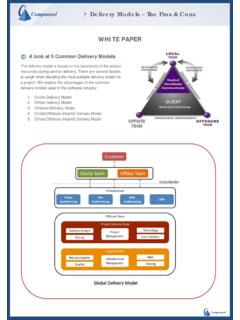
3 This application guide provides direction for the Fiber Optic cabling used in a CPwE a data transport medium, optical Fiber is an integral part of a CPwE deployment. Fiber provides the connectivity for a wide variety of connection types and offers several benefits within a CPwE architecture. By bringing the CPwE architecture to market, Cisco and Rockwell Automation help manufacturers meet the challenges of a fully-integrated IACS and realize the business benefits standard networking offers. CPwE can also help manufacturers achieve the benefits of cost reduction using proven designs that facilitate quicker deployment while helping to reduce risk in Deploying new 1 shows the CPwE logical framework, which incorporates all elements of a standard plant-wide network.
4 The CPwE logical framework segments devices and equipment into hierarchical functions. This framework also identifies Levels of operations and defines logical plant network Zoning (segmentation) based on functional and security areas. In this document, the CPwE term Industrial Zone is used generically to represent applications such as IACS, process automation systems (PAS), and supervisory control and data acquisition (SCADA). This application guide can be viewed as an extension to the CPwE Deploying a Resilient Converged Plantwide Ethernet Architecture Design and Implementation Guide ( ).
5 Plant-wide deployment of EtherNet/IPTM requires an industrial network design methodology, which helps create a structured hierarchy to support real-time network performance. In addition, it helps enable the convergence of multiple control and information disciplines, including data collection, configuration, 1. This Fiber application guide. 2 Fiber Optic Infrastructure Application GuideENET-TD003C-EN-P Deploying a Fiber Optic Physical Infrastructure within a Converged Plantwide Ethernet ArchitectureIntroductiondiagnostics, discrete, process, batch, safety, time synchronization, drive, motion, energy management, voice, and video (Figure 1).
6 Figure 1 CPwE Logical FrameworkWhat You Will LearnThis application guide helps designers and installers select and deploy Fiber Optic media in plant environments. It details Fiber Optic network Infrastructure solutions that provide high-performance connectivity options that help increase the integrity and availability of a CPwE architecture at each level of the plant-wide network. To assist designers and installers with planning and implementing a viable network Infrastructure , this application guide focuses on the following three steps for selecting Fiber Optic cabling:1.
7 Determine the correct type of singlemode or multimode and, if multimode Fiber is required, the correct grade of multimode Determine the number of Fiber Optic strands needed in each cable Select the appropriate cable construction for the addition to cable selection, this application guide discusses the connectors, adapters, and patching required for a structured cable deployment. It also explains selection and best practice applications for cable management, pathways, and Fiber Optic enclosures. 3 Fiber Optic Infrastructure Application GuideENET-TD003C-EN-P Deploying a Fiber Optic Physical Infrastructure within a Converged Plantwide Ethernet ArchitectureFiber Optic Cabling Systems OverviewFiber Optic Cabling Systems OverviewA Fiber Optic network generally comprises multiple pieces of equipment interconnected by optical Fiber cabling assemblies.
8 The Fiber channel is the Fiber Optic connection between one piece of equipment and another and includes the entire Fiber assembly. Each channel consists of a pair of fibers that form an individual circuit, with each circuit having a transmit Fiber (typically labeled TX) and a receive Fiber (typically labeled RX). When configured this way, the optical Fiber assemblies in this channel become a duplex type supporting separate transmit and receive CPwE architectures subject matter authorities recommend the use of optical Fiber links between network switches in the Industrial Zone for the following applications.
9 Redundant paths for high availability ring and redundant star optimal resiliency protocol convergence times for switches Electromagnetic noise immunity distance and outdoor cable runsFigure 2LC Duplex Patch CordVarious approaches can be used to configure the channel. For example, a duplex patch cord (Figure 2) may be used to connect two pieces of equipment that are in close proximity to each other. Attention must be given to achieve the correct polarization of the connections, , that the transmit (TX) port of one device attaches to the receive (RX) port of the other piece of equipment and vice versa.
10 This polarization is accomplished by patch cord construction and standardized keying of the connectors. 4 Fiber Optic Infrastructure Application GuideENET-TD003C-EN-P Deploying a Fiber Optic Physical Infrastructure within a Converged Plantwide Ethernet ArchitectureFiber Optic Cabling Systems OverviewFigure 3 Permanent Link DiagramThe typical channel is composed of multiple assemblies connected by a combination of the optical Fiber connectors on the cable assemblies mating into adapters. The adapters are mounted into patch panels or other types of mounting arrangements that provide a mechanically convenient and secure point for the connection.