Transcription of Derivation of MOSFET Threshold Voltage from the MOS ... - …
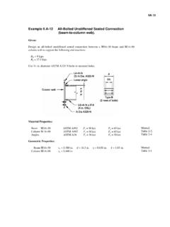
1 Derivation of MOSFET Threshold Voltage from the MOS Capacitor ENEE 313 Notes Prof. Neil Goldsman Threshold Voltage is the Voltage applied between gate and source of a MOSFET that is needed to turn the device on for linear and saturation regions of operation. The following analysis is for determining the Threshold Voltage of an N-channel MOSFET (also called an N- MOSFET ). The analysis is performed with a MOS capacitor like the one shown below. Structure MOS Capacitor: Top layer is N-type polysilicon or metal. For this Derivation we will assume it is heavily doped N-type polysilicon with doping ND S1O2 (oxide) insulation sandwiched between two conductors The bottom layer is P-type semiconductor of doping NA We will relate the built-in potential of the device to the Voltage drop across the three layers.
2 Since we have not added any external voltages, the total drop will be due to the built-in potential only. The total potential drop is the sum of the drops over different layers. ()()()14 122334 = + + (1) ()()12polypoly= = drop across poly 0 = (2) ()23 drop across oxideox == (3) ()34 drop across P-type siliconSi = = (4) 143 Define , , &-npsbinp ==== (5), where s=surface between p-Si and SiO2 AiNlnbuilt in potential on P-substratenpThV = = (6) s is the potential at the surface between the p-Si and SiO2 Summing all the drops we write the built in potential as () = total potential = = + = + (7) Now we know the built in Voltage in terms of two unknowns &.
3 OxSi Our goal now will be to reduce the number of unknowns, and eventually determine the built in Voltage as a function of the surface potential s only. We now need to find ox , we know ()32ox 32 Exoxoxox oxxdxExxE t == = (8) ()constant because the is no charge in oxideoxE= Now need to find oxE. So the next ten or so lines of equations are written to determine oxE. Start by using Gauss law 33oxoxSiSixxxxEE === (9) We can calculate SiE at interface Use depletion approximation to calculate SiE. In the silicon under the oxide the p-type material is depleted due to the built in potential. Thus, there is charge there due to acceptor ions since the holes are absent.
4 Use the depletion approximation to solve for the field in the silicon due to the ionized acceptors. The width of the depletion region is wD. Starting with the Poisson equation, while using the approximation that n=0, p=0 in the depletion region, we have: ()()()()()( )()43 SiAsiSi3siSi3siSi3sidE-q =N(10)dxqE(11)qE(12)E(13)111q of depletion region=(14)222 ADADxSixSiDADDxNwxxxNwxdxbase heightEx wN ww =+ == == Solve for Dw ()1212AA22qNqNSiSiDSispw == (15) Finally, substituting wD of (15) into equation (12), we have some usable expression for field in terms of the surface potential: ()()12A12A2qN1 2 qNSiSiSioxSiAspoxoxSiSispoxqEEN == = (16) Note that all terms in (16) except for the surface potential are determined by the manufacturer, or are material constants.
5 Finally we can now find ox ()()1212AA12qN2qNoxoxox oxSispSispoxoxtEtC == = (17) where oxoxoxCt = is the capacitance of the oxide capacitance of the MOSCAP per unit area. An important point to notice here is that ox is now written in terms of s , so we have reduced the number of unknowns to one. Now back to original equation ()()12A1 2qN binpoxsiSispspoxC = = + = + (18) bi is also called msFBV = Note that all terms in this equation are now known except for s Include Gate Voltage Now, instead of working with just the built in potential, we add a Voltage VG to the gate of the MOS capacitor.
6 Now the equation for the total electrostatic potential drop across the MOS capacitor is: () = total potential oxSi oxs pV += + = + (19) Of course, since we have added GV, values for ox and Si will change. However, if we look back at equation (18), we see that the only parameter that is not already determined in that equation is the surface potential s . GV will cause the potential at the interface s to change. So we can conclude that the effect of adding a gate Voltage to the MOS capacitor will cause the surface potential to change as shown in equation (20): 1/ 212( )GSiAspspbioxVqNC = + (20).
7 As shown in equation (20), changing the gate Voltage will change the surface potential. This will ultimately change the concentration of electrons at the Si-SiO2 interface, and eventually, for a MOSFET adjust the drain current for the devices. Threshold Voltage Threshold Voltage Definition: THVis the value of GV that will cause the interface potential to be equal in magnitude and opposite in sign to the substrate potential p . Physically this mean that there would now be a mobile electron concentration at the surface that is equal in magnitude to the mobile hole concentration is the p-substrate. When this happens we say that the surface is INVERTED, and the electron channel at the surface is called the inversion layer.
8 So define Threshold Voltage as GTHVV= when sp = (21) Substituting in THV and s , we obtain the following expression for the Threshold Voltage in n-channel mosfets . 121=4 ||+ 2 - CTHSiAppbioxVqN