Transcription of DERM2.0 FOG Plan Review Checklist - miamidade.gov
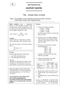
1 FOG Plan Review Checklist Updated 10/24/2018. Not Accepted Accepted N/A. Item / Criteria 1. General Drawings are 11 X17 or larger, legible and include Facility Name, address (include unit/bay) and GDO. permit No. (existing facilities with grease discharge operating permit). Architectural, Civil and Plumbing drawings match (where applicable). Drawings indicate Type of Food Service Establishment, , full service restaurant, cafeteria, bakery, ice cream parlor, day care, etc. All seats (bar, table, booth, etc.) shown and counted. Drive-thru shown (for existing and/or proposed). List/include daily maximum meals for take-out and drive-thru. Existing Labeled Existing and Proposed labeled Proposed.. Projects proposing to use Existing FOG Control Devices (FCDs) include Condition Assessment for each tank/unit.
2 Condition Assessment Forms for Gravity and Hydromechanical tanks available at #4. 2. Plumbing Sheets MDC Code Section (8). Signed/sealed/dated by a Florida Registered-Professional Engineer. MDC Code Sections (8)(a), and Floor plan and Isometric drawings show sanitary and grease drain lines and fixtures (Existing &. Proposed). All appliances connected to plumbing shown and identified (Existing & Proposed). All drainage fixtures identified/labeled. DFUs, slope and diameter shown in plan and isometric (Existing & Proposed). Grease waste line labeled GW to distinguish it from the sanitary (bathroom) waste line. All GW lines connected to a FCD (Existing & Proposed). Sanitary line labeled Sanitary or SS to distinguish it from GW line (Existing & Proposed).
3 All Drainage Fixtures located in food and beverage preparation areas (back of house) are connected to the grease waste line (GW), and routed through a FCD. Drainage fixtures include but are not limited to kitchen sinks (one, two, or three compartment), mop sinks, hand sinks, floor and trench drains, sink drains, dishwasher, pasta stations, etc. Sanitary (bathroom) waste line does not connect to GW lines or FCD. p:\pollution regulation\delegated env permitting\wps\fog control program\fog control plan reviews----------reviews\1_fog Review guides\ Review 1. FOG Plan Review Checklist Updated 10/24/2018. Not Accepted Accepted N/A. Item / Criteria Plumbing Sheets (continuation). FCD shown in plan and isometric drawings (Existing & Proposed).
4 Label as Hydro mechanical or Gravity and indicate installation above ground or below ground. Locations and details for all wash-down areas shown and labeled. All wash-down areas are designed to prevent the release of wash-water and FOG to ground, groundwater, surface waters, or stormwater. Where mat and equipment wash-down is to be performed in a mop sink; the mop sink shall be properly sized and labeled. Locations and details for all stored waste, including yellow and brown grease, shown and labeled. Storage areas designed to prevent the release of FOG to ground, groundwater, surface waters or storm sewers. Storage containers are identified by waste type and capacity in gallons and sized to prevent overfilling.
5 All storage containers have a lid that prevents rainwater inflow. Plans shall show quantity of yellow and brown grease generated, with cleaning/emptying of the storage container frequency at 90% capacity of the container or sooner. Where the horizontal run from the source of food waste and FOG is greater than 100 feet, provisions for preventing clogging by FOG and other waste is included. Where the horizontal run from the source of FOG is greater than 50 feet from the solids separator or FOG control device, plans show access points every 50 feet measured center-to-center. Details for access point provided in drawings. Where the FOG control device is located at a different floor or at a horizontal distance exceeding 100.
6 Feet from the back of the house area, an Interceptor Monitoring Alarm or Device is provided. Plan profiles and sections demonstrate how all labels and markings on FCDs remain visible during and after installation. Effective Volume, material of tank and all appurtenances ( , inlet/outlet, cover, etc.), Plan and Elevation Details and dimensions ( , length, width, depth, inlet/outlet dimensions), and DOH Number shown. ). Gravity FCDs located outside per FAC Rule 64E-6. Material of the interceptor compatible with the waste stored (pH of ). Specifications for concrete protective liners mechanically anchored or coatings Gravity FCD indicate that it is for wastewater immersion, approved for use in wastewater wet wells, pump stations, manholes, AND for corrosion/acid protection, not simply waterproofing or damp-proofing.
7 Plans indicate that coating application will be by the manufacturer. For proposed concrete precast FCDs, the precast concrete plant name and precast concrete plant certifying agency accepted by the Florida Department of Transportation (NPCA, CCI and PCI*1) is shown and labeled accordingly. *1. p:\pollution regulation\delegated env permitting\wps\fog control program\fog control plan reviews----------reviews\1_fog Review guides\ Review 2. FOG Plan Review Checklist Updated 10/24/2018. Not Accepted Accepted N/A. Item / Criteria Plumbing Sheets (continuation). Make/Model No., PDI/ASME/CSA Certification, Flow Rate (gpm), FOG Capacity (lbs) at 99% grease removal efficiency shown in plumbing plans. Every Unit Must Show/Install Vented Flow Control/Air Inlet Not Just First!
8 Hydromechanical Solids separation is provided prior to existing or proposed FOG control devices FCD. that require a flow control device or that are not certified to handle solids. FOG control devices installed below ground/grade to intersect the building grease waste drain. Sampling Point located after the point of no further treatment, shown in plan and isometric drawings and labeled. When more than one FCD, a compliance sampling point is required after the flow from all FCDs are combined (excluding sanitary lines). Sampling point detail shall be provided and be consistent with pipe sizes. The sampling point shall be directly accessible for visual inspection and sampling. Minimum diameter for the vertical axis is 4-inches.
9 Minimum clearance for sampling port is 3 ft horizontal and 4 ft feet vertical and shall be shown in plans. Note that utilizing DERM's retrofit sampling point detail is not mandatory. The engineer of record shall design/select the most appropriate sampling point design to assure consistent and representative sampling results based on site-specific facility and operation conditions. Access to Sampling Point shown in plan and elevation Minimum 4-ft vertical and 3-ft horizontal clearance required. Access to FCD shown in plan and elevation. Minimum 4-ft vertical and 3-ft horizontal clearance required. Horizontal clearance may be equivalent to the width of the FCD but not less than 30-inches. Where the FOG control device will serve multiple users/tenants, each user/tenant shall be identified and their flows and loading rates shall also be included on the plans.
10 Clearly detail capacity allocated to this project/facility, and capacity for other facilities. Provide address with bay/unit number of all the facilities. FCD sizing calculations shall be provided and include cleaning (pump-out) frequency. Refer to sizing requirements below. All assumptions, factors, variables and information used to size system shall be included. Minimum information is provided below. p:\pollution regulation\delegated env permitting\wps\fog control program\fog control plan reviews----------reviews\1_fog Review guides\ Review 3. FOG Plan Review Checklist Updated 10/24/2018. Not Accepted Accepted Item / Criteria N/A. 3. Gravity FCD Sizing [MDC Section (9)(a) and (b)]. FCD(s) proposed shall comply with minimum and maximum size (effective volume) requirements of 64E6, FAC.