Transcription of Description DP/DP Coupler Version: 11/1998 …
1 Description DP/DP CouplerVersion: 11/1998 Copyright Siemens AG 1997 All Rights ReservedPage 1 of 34DP/DP CouplerUser DescriptionVersion DP/DP CouplerVersion: 11/1998 Copyright Siemens AG 1997 All Rights ReservedPage 2 of 34 Liability ExclusionWe have checked the contents of this document for agreement with thehardware and software described. Nevertheless, deviations can't beexcluded, and we are not assuming responsibility for completeagreement. The data in the document is checked regularly, corrections are included in subsequent editions. Wegratefully accept suggestions for Siemens AG 1997. All rights reservedUnless permission has been expressly granted, passing on thisdocument or copying it, or using and sharing its content, is not will be held liable.
2 All rights reserved, in the event a patent isgranted, or a utility model or design is to technical DP/DP CouplerVersion: 11/1998 Copyright Siemens AG 1997 All Rights ReservedPage 3 of 34 Description DP/DP CouplerTable of Contents1. NOTES ON CE EU Guideline EMC 89/336/European Economic Areas of Following the Installation Installing the Working on Note to the Manufacturer of EU Guideline "Machines" 89/392/EWG62. GENERAL73. SETTINGS ON THE Setting the Slave Address and LED Setting the Data Length114. Components Commissioning125. CONFIGURING WITH COM Handling the Device Description Data File and the Type Configuration Example156.
3 CONFIGURING WITH Handling the Device Description Data Configuring Example19 Description DP/DP CouplerVersion: 11/1998 Copyright Siemens AG 1997 All Rights ReservedPage 4 of 347. Connector Assignment of the RS485 Interfaces (X1, X2) Connector Assignment of the Power Supply (X3)248. TECHNICAL Mechanical Environmental Order Number259. CONTACT Personal Contact Siemens Additional Addresses2710. English2811. Appendix A - Device Description Data Appendix B - Type File33 Description DP/DP CouplerVersion: 11/1998 Copyright Siemens AG 1997 All Rights ReservedPage 5 of 341. Notes on CE EU Guideline EMC 89/336/European Economic CommunityThe following applies to the interface described in these operating instructions:Products that bear the CE marking meet the requirements of the EU Guideline89/336/EWG "Electromagnetic Compatibility" and the harmonized European standards(EN) listed to the aforementioned EU Guideline, Article 10, the EU conformitydeclarations are kept at the disposal of the proper agencies at the following location.
4 Siemens AktiengesellschaftAutomation Engineering DivisionAUT E147 Postfach 1954D-92220 Areas of ApplicationThe interface modules are designed for industrial use, and meet the following requirements:Area of ApplicationRequirements forEmitted InterferenceInterference ImmunityIndustryEN 50081-2 : 1993EN 50082-2 : 1995 With an individual permit, the interface module can also be used in residential areas(residential-, commercial- and trade sector, small industries).Area of ApplicationRequirements forEmitted InterferenceInterference ImmunityResidential AreaIndividual PermitEN 50082-1 : 1992 You'll have to get the individual permit from an agency or a testing center.
5 In Germany, theFederal Agency for Postal Service and Telecommunication and its branches grant theindividual DP/DP CouplerVersion: 11/1998 Copyright Siemens AG 1997 All Rights ReservedPage 6 of Following the Installation GuidelinesThe DP/DP Coupler meets the requirements if you do the following:1. Follow the installation guidelines provided in the operating instructions for installationand In addition, follow the rules below for mounting the device and for working on Installing the DeviceInterface modules have to be installed in electrical apparatus rooms or in enclosed casings(for example, control boxes made of metal or plastic).In addition, you have to ground the device and the control box (metal box), or at least thetop hat rail (plastic box) to which the interface was Working on CabinetsTo protect the modules from the discharge of static electricity, the employees have todischarge themselves electro-statically before opening cabinets or control Note to the Manufacturer of GeneralThe DP/DP Coupler does not represent a machine in the sense of the EU Guideline"Machines".
6 There is, for that reason, no conformity declaration regarding the EU Guideline"Machines" 89/392 EU Guideline "Machines" 89/392/EWGThe EU Guideline "Machines" 89/392/EWG regulates the requirements for a machine. Amachine is defined there as a totality of connected parts or devices (refer also to EN292-1,Paragraph ).The DP/DP Coupler is part of the electrical equipment of a machine, and the machinemanufacturer has to include it in the process of the conformity DP/DP CouplerVersion: 11/1998 Copyright Siemens AG 1997 All Rights ReservedPage 7 of 342. GeneralThe DP/DP Coupler is used for connecting two profibus DP networks, and to thustransmit data from the master of the one network to the master of the other.
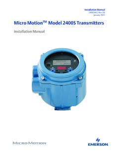
7 The maximumvolume of data that can be transmitted is, in sum, 256 bytes. A maximum of 244 bytes canbe transmitted in one configuring tools can be used for configuration. There, the DP/DP Coupler isconfigured as a modular slave. With the configuring mask, the desired length of the inputand output data can be set. The output data of the one slave is transferred as input data tothe respective other slave, and vice figure below shows the mode of operation in (1)=1 MasterPROFIBUS-DP (Net 1) MBdDrivePB (1)=4 SlaveET200PB (1)=6 SlaveET200PB (1)=5 SlavePROFIBUS-DP (Net 2) 12 MBdDrivePB (2)=4 SlaveET200PB (2)=3 SlaveET200PB (2)=5 SlavePB (1)=3 SlavePB(2)=50 SlavePossible PROFIBUSNet Addresses 1-125 Possible profibus -Net Addresses 1-125DP/DP CouplerSIMATICPB(2)=1 MasterFigure 1: Interfacing Two profibus DP Networks with the DP/DP CouplerThe following example shows that both networks are independent of each other.
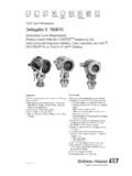
8 Thismeans: a separate address for each profibus DP network has to be set. In the figurebelow, this is Address "3" for Network 1, and Address "50" for Network 2. In addition, ineach network you can process with a different baudrate, since it is a question of 1 fills the output buffer more slowly than it is emptied by Network 2. Network 2thus reads the identical data several times in succession. It is the other way around in thedirection from Network 2 to Network 1. The output buffer is overwritten several timesbefore it is emptied by Network 1. The data written last is thus always is to be taken that the input and output areas of both networks are harmonized withone DP/DP CouplerVersion: 11/1998 Copyright Siemens AG 1997 All Rights ReservedPage 8 of 34 Note:When configuring the DP/DP Coupler , please make sure that both networks are configuredindependent of each this can be done with completely different tools, no consistency check is AreaPROFIBUS-DPNet 1 Output AreaPROFIBUS-DPNet 2 Input AreaPROFIBUS-DPNet 2 Input AreaPROFIBUS-DPNet 116 Bytes16 Bytes8 Bytes8 BytesPROFIBUS-DPNet 212 MBaudPROFIBUS Address 3 profibus Address 50 Figure 2.
9 Mode of Operation in Principle - Example3. Settings on the Setting the Slave Address and DiagnosticsThe slave address for the two slaves is set independent of each other with DIP switchesthat are located on the top side of the device. The addresses should be set between 1 DP/DP CouplerVersion: 11/1998 Copyright Siemens AG 1997 All Rights ReservedPage 9 of 34 Example:For DP Network 1, Address 3 is to be set. Diagnosis = DP Network 2, Address 50 is to be set. Diagnosis = 3: Top Side of Device - Example for Setting the profibus AddressesDiagnostic:Dip switch for diagnostic set to 1 means:Indication for the master on either side(wherever selected) that data are valid.
10 The indication isdone in the LSB of the first byte within the data exchange. The LSB is always 1 . If thecommunication to the device will be interrupted the LSB would be 0 within the purpose of this bit is an easy and fast control for the application programm to know aboutthe status of the Slave. For more detailed information the diagnostic can be used. Dependingon the application and the selected master system this method of reporting a simple statusinformation is an easy was to report device existing or not . By using a master system which isable to handle diagnostic data this bit is not recommended to use. 1 2 4 8 16 32 64 1 1 2 4 8 16 32 64 2 Explanation:Net 1 = DP1.