Transcription of DESCRIPTION - UPGNET
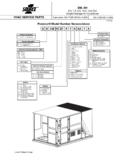
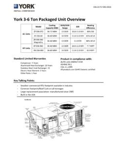
1 TECHNICAL SINGLE STAGEGAS-FIRED RESIDENTIAL MULTI-POSITION GAS FURNACESMODELS: TG9 SNATURAL GAS40 - 130 MBH INPUTDue to continuous product improvement, specifications are subject to change without us on the web at rating information can be found at limited warranty on both heat exchangers to the orig-inal purchaser; a 20-year limited warranty from original instal-lation date to subsequent warranty on the heat exchanger in commercial 5-year limited Parts 10-year limited parts warranty when product isregistered online within 90 days of purchase for replacement or closing for new home DISTRIBUTION USE ONLY - NOT TO BE USED AT POINT OF RETAIL SALEDESCRIPTION These compact units employ induced combustion, reliable hotsurface ignition and high heat transfer aluminized tubular heatexchangers. The units are factory shipped for installation inupflow or horizontal applications and may be converted fordownflow furnaces are designed for residential installation in abasement, closet, alcove, attic, recreation room or garage andare also ideal for commercial applications.
2 All units are factoryassembled, wired and tested to assure safe dependable andeconomical installation and units are Category IV listed and may be vented eitherthrough side wall or roof applications using approved plasticcombustion air and vent Easily applied in upflow, horizontal left or right, or downflow installation with minimal conversion necessary. Compact, easy to install, ideal height 33" tall cabinet. Blower-off delay for cooling SEER improvement. Easy access to controls to connect power/control wiring. Built-in, high level self diagnostics with fault code displays standard on integrated control module for reliable operation. Low unit amp requirement for easy replacement application. Single wire twinning or staging feature available. All models are convertable to use propane (LP) gas. Electronic Hot Surface Ignition saves fuel cost with increased dependability and reliability.
3 100% shut off main gas valve for extra safety. 4 speed, direct drive PSC motor. 24V, 40 VA control transformer and blower relay supplied for add-on cooling. Hi-tech tubular aluminized steel primary heat exchanger. Secondary heat exchanger made of corrosion resistant stainless steel materials. Timed on, adjustable off blower capability for maximum com-fort. Blower door safety switch. Solid removable bottom panel allows easy conversion. Airflow leakage less than 1% of nominal airflow at duct-blaster conditions. No knockouts to deal with, making installation easier. Movable duct connector flanges for application flexibility. Quiet inducer operation. Inducer rotates for easy conversion of venting options. Fully supported blower assembly for easy access and removal of blower. External air filters used for maximum flexibility in meeting customers IAQ needs. Protection included from air intake, exhaust vent, or conden-sate blockage.
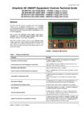
4 Venting applications - may be installed as either 2-pipe (sealed combustion) or single-pipe vent (using indoor com-bustion air). No special vent termination required. 1/4 turn knobs provided for easy door removal. Internal condensate trap design (patent pending) provides condensate management options, easy visual operation, and is self-priming to prevent nuisance Controls Unitary ProductsAnnual Fuel Utilization Efficiency (AFUE) numbers are determined in accordance with DOE Test size and over current protection must comply with the National Electrical Code (NFPA-70-latest edition) and all local furnace shall be installed so that the electrical components are protected from SIDEC ombustion Air InletCondensate Drain(Downflow)Vent Gas PipeEntryElectricalEntryCondensateDrainT hermostatWiringRIGHT SIDEVent OutletCondensate Drain(Downflow)14 1 23 Combustion Air InletGas PipeEntryElectricalEntryCondensateDrainO ptional Return AirCutout (Either side) CSUPPLY.
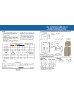
5 56 20 B3 .56 CombustionAir InletVentOutletRETURN Cabinet & Duct DimensionsModelsNominalCFM (m3/min)CabinetSizeCabinet Dimensions (Inches)ApproximateOperating WeightsABCLbsTG9S040A08MP11800A14 1/213 3/811 3/4113TG9S060A10MP111000A14 1/213 3/811 3/4118TG9S060B12MP111200B17 1/216 3/813 1/4122TG9S080B12MP111200B17 1/216 3/814 3/4126TG9S080C16MP111600C2119 7/816 1/2136TG9S080C22MP112200C2119 7/816 1/2139TG9S100C16MP111600C2119 7/818 1/4142TG9S100C20MP112000C2119 7/818 1/4145TG9S120D16MP111600D24 1/223 3/821 3/4153TG9S120D20MP112000D24 1/223 3/821 3/4156TG9S130D20MP112000D24 1/223 3/8No Hole160 Ratings & Physical / Electrical DataModelsInput OutputAFUE%Air Temp. RiseMax. OutletAir TempBlowerBlower SizeMax Over-Current ProtectTotal UnitAmpsMin. wire Size (awg) @ 75 ft one wayMBHMBH F Controls Unitary Products3 FILTER PERFORMANCEThe airflow capacity data published in the Blower Perfor-mance tables shown represents blower performance WITH-OUT applications of these furnaces require the use of fieldinstalled air filters.
6 All filter media and mounting hardware orprovisions must be field installed external to the furnace cabi-net. DO NOT attempt to install any filters inside the Air velocity through throwaway type filters may not exceed 300 feet per min-ute ( m/min). All velocities over this require the use of high velocity Do not exceed 1800 CFM using a single side return and a 16x25 filter. For CFM greater than 1800, you may use two side returns or one side and the bottom or one return with a transition to allow use of a 20x25 filter.*- 24" clearance in front and 18" on side recommended for service furnaces approved for alcove and attic (LP) Conversion Kit - This accessory conversion kitmay be used to convert natural gas (N) units for propane (LP) - All Models except 130K ModelS1-1NP0501 - 130K ModelConcentric Vent Termination - For use through rooftop, side-wall.
7 Allows combustion air to enter and exhaust to exit throughsingle common hole. Eliminates unslightly elbows for a (2") & S1-1CT0302-636 (2")S1-1CT0303 (3") & S1-1CT0303-636 (3")Sidewall Vent Termination Kit - For use on sidewall, two-pipeinstallations only. Provide a more attractive termination for loca-tions where the terminal is visable on the side of the (3")S1-1HT0902 (2")Condensate Neutralizer Kit - Neutralizer cartridge has a 1/2"plastic tube fittings for installation in the drain line. Calcium car-bonate refill media is also available from the Source 1 Parts (p/n 026-30228-000).1NK0301 Side Return Filter Racks - S1-1SR0200 - All ModelsS1-1SR0402 - All ModelsBottom Return Filter Racks - 1BR05xx series are galvanizedsteel filter racks. 1BR06xx are pre-painted steel filter racks tomatch the appearance of the furnace or 1BR0614 - For 14-1/2 cabinetsS1-1BR0517 or 1BR0617 - For 17-1/2 cabinetsS1-1BR0521 or 1BR0621 - For 21 cabinetsS1-1BR0524 or 1BR0624 - For 24-1/2 cabinetsCombustible Floor Base Kit - For installation of these fur-naces in downflow applications directly onto combustible floor-ing material.
8 These kits are required to prevent potentialoverheating floor base kit provides access forcombustible - For 14-1/2 cabinetsS1-1CB0517 - For 17-1/2 cabinetsS1-1CB0521 - For 21 cabinetsS1-1CB0524 - For 24-1/2 cabinetsEAC Transition Kits - For installation of EAC accessories withthese furnaces to provide easy transition of return airflowthrough the EAC to get the proper sealing and reduced - For all models using side returnS1-1TK1014 - For 14-1/2 cabinets using bottom returnS1-1TK1017 - For 17-1/2 cabinets using bottom returnS1-1TK1021 - For 21 cabinets using bottom returnS1-1TK1024 - For 24-1/2 cabinets using bottom returnHigh Altitude Pressure Switches - For installation where thealtitude is less than 5,000 feet it is not required that the pres-sure switch be changed. For altitudes above 5,000 feet, see - 060S1-1PS3307 - 040, 080S1-1PS3302 - 100, 120, 130 Thermostats - Compatible thermostat controls are availablethrough accessory sourcing.
9 For optimum performance andinstallation, refer to the UPGNET Low Voltage Wiring Diagram document to select and apply side return above 1800 CFM is approved as long asthe filter velocity does not exceed filter manufacturer s rec-ommendation and a transition is used to allow use on a20x25 Filter Sizes (High velocity 600 FPM)CFMC abinetSizeSide(in)Bottom(in)800A16 x 2514 x 251000A16 x 2514 x 251200A16 x 2514 x 251200B16 x 2516 x 251600B16 x 2516 x 251600C16 x 2520 x 252000C(2) 16 x 2520 x 252200C(2) 16 x 2520 x 252000D(2) 16 x 2522 x 25 Unit Clearances to CombustiblesApplicationUpflowDownflowHor izontalTop1" 0" 0" Vent0" 0" 0" Rear0" 0" 0" Side0" 0" 1" Front*0" 0" 0" FloorCombustibleCombustible11.
10 For combustible floors only when used with special ContactNoNoYesNOTICE400991-YTG-E-02104 Johnson Controls Unitary Products1. Airflow expressed in standard cubic feet per minute (CFM).2. Motor voltage at 115 Performance CFM - Any Position (without filter) - Bottom ReturnModelsSpeedBottom Airflow Data (SCFM)Ext. Static Pressure (in. H2O) High 1128 1077 1035 996 950 891 842 781 708 646 Medium High 934 909 867 834 818 780 745 696 631 584 Medium Low 746 735 714 679 653 629 596 585 547 494 Low 676 652 627 601 581 542 516 474 441 383 TG9S060A10MP11 High 1360 1290 1230 1165 1103 1043 983 925 820 776 Medium High 1251 1198 1140 1089 1038