Transcription of Design and Construction of a Space-frame Chassis
1 Design and Construction of a Space-frame Chassis Brendan. J. Waterman 20348559. School of Mechanical and Chemical Engineering University of Western Australia Supervisor: Assoc/Prof Adam Wittek School of Mechanical and Chemical Engineering University of Western Australia Final Year Project Thesis School of Mechanical and Chemical Engineering University of Western Australia Submitted: November 7th, 2011 . 1. Abstract The purpose of this project is to Design and build a Space-frame Chassis for a race car to compete in the FSAE-A competition as part of the UWA REV team. The FSAE. competition is a competition for university students to Design , build and race their own open wheeled race cars, there are also a number of static Design events in the competition.
2 The 2011 REV FSAE car will be powered by four electric motors with one mounted to each wheel's upright. This is a new configuration for a FSAE car and as such requires an entirely new Chassis Design that both supports the loads placed on it but also weighs as little as possible. The Chassis Design implements structural battery boxes which have the dual purpose of protecting the driver from the batteries and adding strength to the frame, this has not previously been used in any other FSAE car. Using these stressed battery boxes gives the Chassis excellent torsional stiffness, yet the entire frame still weighs just over 40kg.
3 2. Acknowledgements I would like to thank Adam Wittek for his advice throughout this project, the REV team and Swan Energy for funding the team for which the Chassis has been designed, Ian Hooper for assisting with and providing the tools and facilities used for Construction and Ed Farrar for aiding in and providing the press used for weld testing. Finally I would like to thank my family and partner for their support throughout the duration of my studies. 4. Contents Abstract .. 2. Letter of Transmittal .. 3. Acknowledgements .. 4. Introduction .. 7. Literature Review .. 10. Design Process.
4 11. 11. Suspension Design and Forces .. 15. Packaging .. 17. Material .. 17. Manufacture .. 18. Square vs Round .. 19. Triangulation and Stressed Skins .. 20. Stressed Battery Boxes .. 24. Final Design .. 27. Front and rear sections .. 27. Roll hoops .. 33. Side impact structure .. 37. Front Bulkhead and Foot-well .. 38. Completing the Space-frame .. 39. Battery boxes .. 40. Final Design 41. Construction .. 42. Welding .. 42. Construction Process .. 43. Work completed .. 48. 5. 49. Construction .. 49. Operation of the completed Chassis .. 51. Torsion 52. Weld Testing .. 53. Conclusion .. 59.
5 Future work .. 60. Construction .. 60. Chassis testing .. 60. Ultrasonic weld 60. Tuning .. 60. Future designs .. 61. References .. 62. 6. Introduction The purpose of this project is to Design and construct a Chassis for an electric powered Formula SAE (FSAE) car to compete in the December 2011 FSAE-A competition. The competition is for students to Design , build and race small open-wheeled race cars against the clock in a number of events. The competition also includes some static Design events, where the cost and Design of the car is judged by a panel. A unique Chassis Design is required as the car will be powered by four electric hub motors, as opposed to the more conventional internal combustion engine mounted within the frame.
6 This is the first time that electric hub motors will be used in the Australian F- SAE competition and the first time four wheel-hub motors have been used in any FSAE. competition around the world. In 2010 the REV team converted a previously used petrol FSAE Chassis to electric power in a similar configuration to the conventional combustion engine configuration. The Chassis was made by UWA Motorsports and competed in the 2002 F-SAE. competition. It was never intended for this petrol to electric converted car to compete in any FSAE event as it was only done as a prototyping exercise in an effort to investigate the potential of an electric F-SAE car.
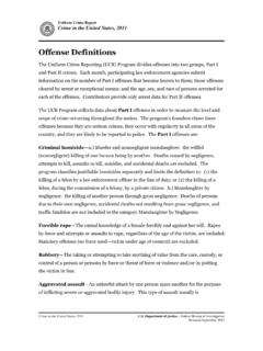
7 The Chassis no longer meets the requirements for the FSAE competition as the rules for the competition have changed since 2002. Figure 1 2001 UWAM Chassis converted to electric power using a conventional inboard engine layout 7. There is much confusion over the meaning of the word Chassis as discussed by Aird in the book The Race Car Chassis (Aird,1997). In the early days of the automobile where coachbuilders were used, the term Chassis was often used to describe the frame, engine and suspension as one complete unit. Essentially it described everything in a car other than the bodywork and cabin.
8 In some other contexts Chassis defines only the frame of the car with the drive-train and suspension being considered entirely separate items. This latter interpretation of the word is what is used throughout this project, where the terms Chassis and frame mean the same thing are interchangeable. When defined as above, a Chassis is the component in a car that everything else attaches to. The most basic, common Chassis Design is referred to as the Ladder Frame due to its resemblance to a conventional lean-to ladder (Adams, 1992). A Ladder Frame consists of two long members that run the length of the automobile and are joined by a set of smaller members perpendicular to the two long members.
9 The other components that make up the vehicle are then mounted to this Chassis . In the case of the Ladder Frame; the body and engine are usually mounted to the top of the Chassis with the suspension being mounted below. This type of Chassis dates back to horse-drawn carriages, originally made of wood, but generally being made of steel in automobiles since the 1900's (Aird 1998). While being simple and easy to manufacture this type of Chassis generally has a poor torsional stiffness which makes it undesirable for a race car. In more recent times the Chassis has evolved and in some cars it can be hard to distinguish between what makes up the body of a vehicle and what makes up the Chassis .
10 A monocoque Chassis uses the body as the load carrying component and means that no separate Chassis structure is needed. Entire panels carry the load rather than specific members, often these panels are the outermost parts of the body which means that a higher polar moment of Inertia (about the axis running from the front to the rear of the car) is achievable. A high polar moment of inertia about the longitudinal axis is a desirable property for a Chassis as it is directly related to torsional stiffness (Aird, 1997). The drawback of a monocoque Chassis is that they can be difficult to manufacture and are comparatively expensive in small production numbers, which is why a monocoque will not be used in this project.