Transcription of Design and Development of Microcontroller Based …
1 RESEARCH INVENTY: International Journal of Engineering and Science ISSN: 2278-4721, Vol. 1, Issue 5 (October 2012), PP 26-33 26 Design and Development of Microcontroller Based Electronic Speed Governor for Genset/ automotive Engine 1 Sushant R. Burje, and 1 Sinhgad College of Engineering, Pune, India 2 Sinhgad College of Engineering, Pune, India 3 automotive Research Association of India, Pune, India Abstract: The engine speed controller of a conventional diesel engine is called a Governor. In order to control engine speed, the governor controls the amount of fuel using fuel rack. The fuel rack is connected to throttle actuator lever and driven from Microcontroller . The actuator motion is controlled to achieve set-point rpm so required pulse width modulation duty cycle to drive actuator is calculated from digital PID algorithm. PIC 16F877A Microcontroller Based hardware is developed for the implementation of the controller.
2 The system broadly involves interfacing hardware and the software for PID algorithm. A continuous PID controller is governed by an equation which describes the dynamic time varying behavior of the input or the error signal. This is digitized using numerical approximations and is programmed in the Microcontroller . This system is a closed loop control system with feedback signal generated by a digital magnetic pickup, which gives a pulse output which is TTL compatible. The PID algorithm along with the hardware achieves the speed control of the diesel engine. The hardware and software are validated in real time by considering different speed settings. Keywords: Electronic Speed Governor, PID, Throttle Actuator, PIC16F877A, Pulse width modulation. I. Introduction The basic task of electronic speed governor system is to prevent the engine from exceeding the maximum revving speed specified by the engine manufacturer.
3 Since the diesel engine always operates with excess air because the intake flow is not restricted, it would overrun if there were no means of limiting its maximum speed. Depending upon the type of governor control system, its functions may also include holding the engine speed at specific constant levels such as idling or other speeds within a specific band or the entire range between idling and maximum speed. A diesel engine is the most common solution for the distributed power generating systems due to its superior fuel efficiency compared to the other types of internal combustion engines. In conventional diesel engine systems, a fly-wheel type governor which is mechanically synchronized with the engine crankshaft has been widely used to control engine speed. However, the electronic governor gradually extends its use in the various applications because of its superior control performance, simple structure, and maintenance free characteristics.
4 In industries, electronic governor with Proportional, Integral, and Derivative (PID) speed controller is generally used for such applications. Electronic speed governor has good speed control performance and is relatively inexpensive. With a diesel engine, there exists no single control-rack position which would permit the diesel engine to maintain its speed accurately within the operating speed range without a governor. At idle, for example, without a governor the engine speed would either drop until the engine stalls, or it would continue to increase until the engine races, culminating in self-destruction. The basic job of every governor is to limit the engine s maximum speed. To achieve stable response of engine the PID (Proportional Integral Derivative) algorithm is implemented. Engine rpm is taken as controlled parameter and throttle angle is taken as controlled variable.
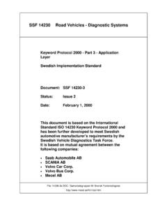
5 The throttle angle is adjusted through throttle actuator via pulse width modulation signal. The pulse width modulation signal is calculated in PID loop. Every time the engine s rpm error is processed in PID loop and required pulse width modulation control signal is calculated. The closed loop system is achieved through feedback from engine rpm. The total set-up of electronic speed governor is shown in Figure 1. Design and Development of Microcontroller Based Electronic Speed Governor for Genset/ automotive Engine 27 Figure 1: Electronic Speed Governor Setup. II. Objective The project is an endeavor towards an effective Design and Development of Microcontroller Based electronic speed governor for genset/ automotive engine. The following are the main objective 1. To Design drivers for both throttle actuator and magnetic pickup sensor. 2. To Design hardware for the system using PIC16F877A Microcontroller .
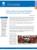
6 3. To develop an experimental setup for mounting of throttle actuator and magnetic pickup sensor. 4. Implement the PID algorithm in embedded C code. 5. Application of the designed algorithm in an embedded controller to verify on actual engine operation. III. System Description The following Figure 2 shows block diagram of working of electronic speed governor system. The magnetic pickup sensor is mounted on engine flywheel. The engine rpm is measured in capture compare module of the PIC Microcontroller . The throttle actuator s lever is directly connected to the engine fuel pump. The throttle actuator is controlled from the pulse width modulation signal so it is directly connected to the RC2 pin of the PIC Microcontroller . The engine rpm is continuously measured and compared with the required set point and when the error signal is generated it is directly processed in the PID algorithm.
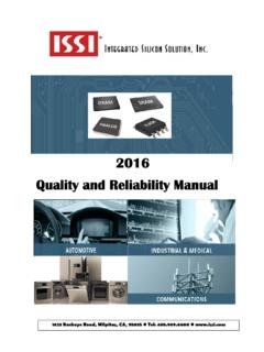
7 The PIC Microcontroller generates the required pulse width modulation duty cycle from the PID algorithm Based on which diesel engine gets stabilized at required set point. The working pulse width modulation period is calculated from initial trails on the throttle actuator. Figure 2: Block diagram of Electronic Speed Governor System. In this project CCP1 (PWM) is used to control the position of throttle actuator. PWM stands for the Pulse Width Modulation where the width of a digital waveform is varied to control the power delivered to a load. The underlying principle in the whole process is that the average power delivered is directly proportional to the modulation duty cycle as shown in Figure 3. The pulse width modulation is required to switching the load devices through MOSFET Based power stage or from any other components. The pulse width modulation has ON time and OFF time and addition of both is period.
8 The average voltage applied to the load is varied from the pulse width modulation which directly depends upon the duty cycle. The time is inversely proportional to the frequency because of which the required period given to the load is in the form of frequency Design and Development of Microcontroller Based Electronic Speed Governor for Genset/ automotive Engine 28 Figure 3: Pulse width modulation with different duty cycle. IV. Design of Controller The improved electronic speed governor system includes digital controller, drive circuit, electromagnetic throttle actuator and the engine speed sensor. The system to be controlled (plant) is the diesel engine. The electronic speed governor is a closed loop system in which feedback is taken from engine rpm. The controller output is in the form of pulse width modulation duty cycle. When the rpm error is generated the required pulse width modulation duty cycle is calculated from PID algorithm.
9 The capture compare module in PIC16F877A is used to calculate engine rpm. The PID update time is kept in proportion with the throttle actuator response time. The key step of the electronic governor Design is to choose the suitable actuator coupled suitably with fuel pump rack. The requirements to actuator of diesel engine governor system are fast response, high accuracy and reliability. Under diesel engine operating principle, the engine speed regulation is achieved by regulating the movement of the pump rack. With electronic speed controller, the movement of pump rack is mainly affected by the diesel engine speed change. P=KPep+KPKI tPe0dt + KP KD dep/dt + Pi (0) (1) where, Pi (0) is the nominal output.
10 A. System to be controlled The system to be controlled is a diesel engine, speed-torque characteristics of which are mentioned in below Figure 4. The PID algorithm is implemented on diesel engine to achieve required set point rpm. The controlled parameter is engine rpm and controlled variable is engine throttle angle. Figure 4: Base diesel engine speed torque characteristics. The diesel engine having idle rpm is 780 with kg/hr fuel flow. The diesel engine produces power up to 52 kW and generates 223 Nm torque at rated engine rpm. The diesel engine works on mechanical governor and having distributor type fuel pump. The above Figure 4 shows the behavior of diesel engine at various loads, the red line shows the engine Torque in Nm. The engine load is directly proportional to the fuel flow. The blue line in Figure 4 shows the fuel flow in kg/hr, which directly increases as engine torque increases.