Transcription of Design and Fabrication of Cooling Tower
1 International Journal of Latest Engineering Research and Applications (IJLERA) ISSN: 2455-7137 Volume 02, Issue 05, May 2017, PP 27-37 2017 IJLERA All Right Reserved 27 | Page Design and Fabrication of Cooling Tower Dileep KJ1, Dileep Kumar Baniya2, Anoop Chandran Kurup3, Arun Varghese4 1234(Department of Mechanical Engineering, Bangalore Technological Institute,India) Abstract: Cooling Tower is a heat rejection device. It is used to dissipate waste heat into the atmosphere. This paper is all about the developing a Cooling Tower that cools the hot water coming from the different equipment in energy conversion lab. In energy conversion lab, there are total five equipments from which we are getting hot water while conducting the experiment. Due to hotness the water is not suitable for experimentation. So the hot water is directly released into the ground without being recirculated.
2 This necessitates the development of Cooling Tower to cool the water. For this purpose a tank used where the hot water coming from the different equipment gets collected. The hot water is then supplied to the Cooling Tower for Cooling by the use of motor pump. The Cooling effect is obtained by the natural air which is entering in the gap provided by the louvers. After the water is cooled it gets collected in another tank which is kept at the bottom of the Cooling Tower . The cooled water is recirculated into the equipment for conducting the experiment. Keywords: Cooling Tower , Equipment, Louver, Motor pump, Tank. 1. Introduction A Cooling Tower is a heat rejection device which extracts waste heat to the atmosphere through the Cooling of a water stream to a lower temperature. Cooling towers may either use the evaporation of water to remove process heat and cool the working fluid to near the wet-bulb air temperature or, in the case of closed circuit dry Cooling towers, rely solely on air to cool the working fluid to near the dry-bulb air temperature.
3 In energy conversion lab there are five different engine in which experiment is conducted. These engine require cold water for conducting the experiment. After successfully completion of experiment hot water comes out from the engine as bi product. Since the water coming from the engines are hot, so this water is not suitable to use in the lab. So this water is discharged in the ground as a waste behind the utilize the water again or to overcome from the water problem, a Cooling Tower is developed. This Cooling Tower will do the work of reducing the water temperature. The water coming from the different engine will be supplied into the Cooling Tower and after Cooling is done again it is supplied into the main stream. The Tower provides a horizontal air flow as the water falls down the Tower in the form of small droplets. The fan centered at the top of units draws air through two cells that are paired to a suction chamber partitioned beneath the fan.
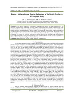
4 The outstanding feature of this Tower is lower air static pressure loss as there is less resistance to air flow. The evaporation and effective Cooling of air is greater when the air outside is warmer and dryer than when it is cold and already saturated. Originally, Cooling towers were constructed primarily with wood, including the frame, casing, louvers, fill and cold-water basin. Sometimes the cold water basin was made of concrete. Today, manufacturers use a variety of materials to construct Cooling towers. Materials are chosen to enhance corrosion resistance, reduce maintenance, and promote reliability and long service life. Galvanized steel, various grades of stainless steel, glass fiber and concrete are widely used in Tower construction, as well as aluminium and plastics for some components. Fig. 1 shows the proposed model of Cooling Tower .
5 Fig. 1 proposed model International Journal of Latest Engineering Research and Applications (IJLERA) ISSN: 2455-7137 Volume 02, Issue 05, May 2017, PP 27-37 2017 IJLERA All Right Reserved 28 | Page 2. Literature survey Seetharamu and Swaroop [1], has found the effect of size on the performance of a fluidized bed Cooling Tower . Application of the principles of the fluidization is made for Cooling towers. The performance on a smaller size Fluidized Bed Cooling Tower (FBCT) is found to be encouraging. Hence a larger size FBCT is designed and the performance is found to be equally good. The pressure drop encountered in FBCT is comparable to that of conventional Cooling towers. The packing height in FBCT reduces considerably because of fluidization. Experiments are conducted in two sizes of Tower column.
6 In the smaller Tower ambient air is forced into the test section by a blower through a diffuser and suitable turning vanes to have a uniform air flow distribution. The flow is regulated by a throttle control valve fitted at the discharge of the blower section. Water is heated in a large tank fitted with electric heaters and fed to the Tower . A spray nozzle is used for uniform distribution of hot water in to the test section. The water flow is regulated by a control valve. The cooled water collected in the basin and returned back to the tank for recirculation . Air flow is measured by a flow nozzle placed at the entry to the blower. Water flow is measured by a orifice plate with differential mercury manometer at the hot water entry to the Tower . Trappings are provided to fit thermocouples and also to make pressure drop readings. Digital multivoltmeters and multiple junction manometers are used for their measurements.
7 A back up thermometer is used for temperature measurement. Psychrometer is used for wet bulb and dry bulb temperature measurements. Ramkumar and Ragupathy [2],did Experiment on the thermal performance of forced draft counter flow wet Cooling Tower with expanded wire mesh type packing. The packing used in this work is Vertical Orientations Wire Mesh Packing (VOWMP) and Horizontal Orientations Wire Mesh Packing (HOWMP). The packing is m height and having a zigzag form. From the experiments it is concluded that the vertical orientation of the packing enhance the performance of the Cooling Tower . Performance of the Cooling Tower was analyzed with expanded wire mesh packing with two different orientations. From the experimental results, the VOWMP is having better performance than HOWMP. It is due water passing over the flank angle of the wire mesh fills and fine water droplets formed in the VOWMP.
8 In VOWMP the water droplets are split into fine size compared with HOWMP. The air to water contact is more in VOWMP, so better heat transfer has been occurred and the Cooling water outlet temperature is reduced compared with HOWMP. From the experimental study the efficiency of the Cooling Tower and Cooling Tower characteristics are higher in VOWMP due to higher contact area of water to air. Up to Liquid/Gas (L/G) ratio because of better contact area between airs to water the drop in performance of the Cooling Tower is less. Above L/G ratio, the Cooling Tower performance was decreased drastically due to large quantity of water and lesser quantity of air. For that reason the contact area between airs to water is in improper ratio. The L/G ratio up to , the VOWMP performance is good and over L/G the performance is dropdown. The present study can be extended with different pitch of the mesh and different size of the diamonds shape.
9 Nagam and Hayder [3], they found experimentally and theoretically heat and mass transfer characteristics of the Cooling Tower . Through experimentation they absorbed the variation of outlet air temperature with air flow rate at different inlet water temperature tends to decrease with increasing air flow rate. However, for high air flow rate region, decreasing rate of outlet air temperature decreases. At specific air and water flow rates and inlet air temperature, effect of inlet water temperature on the outlet air temperature is very small. The reasonable agreement is obtained from the comparison between the predicted results and the present experimental data. It can be seeing that the model give high accuracy relatively with real results (experiment results). The Tower effectiveness increased with the temperature ratio because the outlet water temperature decreases as airflow rate increases number of transfer unit increases as the temperature ratio increases at different L/G.
10 However, trends of curves become cajole as L/G decreases. The pressure drop increasing with increasing airflow rate at different temperature. Variation of outlet air temperature with airflow rate at different inlet water temperature tends to decrease with increasing airflow rate. 3. Design of Cooling Tower The Design of Cooling Tower is based on the following parameter Mass flow rate = 10 LPM = 10 60 LPH Mass flow rate = 600 LPH Mass flow rate = 10 -4 m3 /sec Mass flow rate = 10-4 1000 Mass flow rate = Kg/sec Where 1 m3/sec = 1000 Kg / sec Surrounding condition = 5% WBT & 28 C Taking 80% load condition the average temperature of hot water coming from the engine is 65 C. Water inlet temperature from Cooling Tower , T1 = 65 C International Journal of Latest Engineering Research and Applications (IJLERA) ISSN: 2455-7137 Volume 02, Issue 05, May 2017, PP 27-37 2017 IJLERA All Right Reserved 29 | Page Assuming, Water outlet temperature to Cooling Tower , T2 = 60 C Assumption, Tower base dimension = 1 m 1 m Fan capacity = m3/ sec Step: 1 Water loading (L) Water loading: L = Mass flow rateArea (1) Mass flow rate, M = Kg/sec Tower Area, A = 1 m 1 m = 1 m2 L = L = kg/m2sec Step: 2 Air loading.