Transcription of Design and Manufacture of Testing Equipment for …
1 Design and Manufacture of Testing Equipment for Switchgear By Terry Cousins and Luis Valentim, TLC Engineering Solutions Abstract Switchgear is a key component in electrical power systems. It is essential to verify performance after Design , Manufacture or repair. This paper will discuss a range of automated Testing Equipment that are used to test switchgear. The test Equipment has been designed and manufactured in South Africa in collaboration with switchgear manufacturers and Testing authorities. Automated analysis of the measurements as well as archiving of results for future recall and comparison will be presented. Introduction The definition of switchgear includes electrical disconnects, fuses and circuit breakers used to isolate electrical Equipment .
2 Circuit breakers are mechanical devices connected to the electrical system, where they must provide a suitable path for the flow of the electric current as well as provide protection and control of the electric circuit by either initiating or stopping the current flow. Circuit breakers Design and performance verification requires specific tests to be performed. This paper will present a range of Testing systems for circuit breakers from the instrumentation and data acquisition perspective. Circuit Breaker Testing Circuit breakers are designed and manufactured to operate correctly under a range of conditions. These include switching currents up to the rated load, as well as interrupting overload or fault currents several times the rated current.
3 In the event of a malfunction, the circuit breaker as well as parts of the electric system may sustain severe damage. It is therefore essential to have a high degree of confidence in the performance of any circuit breakers. This confidence level can only be attained by years of operating experience, or by extensive Testing under conditions that simulate those that are encountered in the field applications. Testing will usually be performed to ensure compliance with a local or international standard. Special tests may also be performed by manufacturers to evaluate new designs. The tests that are common to most circuit breakers include: Mechanical Operation o Performance of the mechanism to open and close contacts o Endurance of the mechanism Electrical Operation o Ability to operate safely with rated loads o Ability to safely isolate overloads and short circuits Mechanical Testing The most basic function of any circuit breaker is to open and close the contacts on command.
4 According to a CIGRE report [1] more than 90% of circuit breaker failures are attributed to mechanical causes. These findings confirm the fact that circuit breakers are primarily mechanical devices that are called upon to perform an electric function. Most of the time circuit breakers remain closed and simply act as electrical conductors. When the breaker performs a protective function, from the combined electrical and mechanical point of view, the contact structure is probably the most essential and critical component. A second and equally important component is the operating mechanism employed to produce the motion of the contacts. A circuit breaker is designed to interrupt a short circuit current. The fault energy is proportional to the square of the fault current times the duration of the fault.
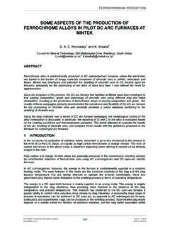
5 The breaker should clear the fault in the minimum time to limit fault damage. This requires that the breaker must operate at a speed greater than a specified minimum speed determined by the Design . The current must also be interrupted in such a way that the arc does not re-strike. The interrupting time or breaking time of a circuit breaker has a common definition according to ANSI and IEC. It consists of the time, from the instant the trip coil is energized to the instant of complete interruption of the current flow through the circuit breaker (taking into account the maximum arcing time required for interruption). Note that the contact parting time, as defined by ANSI, is the summation of the relay time plus the opening time. These relationships are illustrated in Fig.
6 1 below [2]. Fig 1: Interrupting Time Relationships The opening and closing velocities, as well as stroke, or travel distance, are the most important operating characteristics of a circuit breaker. They are dictated primarily by the requirements imposed by the contacts. Opening and closing velocities are important to the contacts in order to avoid contact erosion as well as contact welding. Since contact stroke is synonymous with contact gap, circuit breaker stroke is primarily related to the ability of the circuit breaker to withstand the required operating dielectric stresses. The opening and closing motion curve of a circuit breaker is shown in Fig. 2 [3]. Fig. 2: Circuit Breaker Open and Closing Motion Open / Close Speed Test This test is performed to confirm the key mechanical parameters of the switchgear.
7 This includes the open and close speeds, travel distance and contact closing and parting times. Equipment for performing this test consists of: Computer Equipment with application software for performing the test and analysing the results Displacement transducer for measuring the travel of the circuit breaker Continuity measurement for measuring the contact open and closing Control circuit and power supply for energising the trip and close coils Current clamps to measure trip and close coil currents The Equipment is shown below in Fig. 3. Fig. 3: Test Equipment for Open / Close Speed Test The test system also requires a power supply to energise the close and trip coils as well as a supply for charging the mechanism. The travel measurement is obtained by connecting a linear displacement transducer to the contact mechanism.
8 The output of this transducer is then calibrated to correspond with the distance moved by the contacts. A typical graphic display from the test is shown in Fig. 4. Fig. 4: Open / Close Speed Trace The upper trace is the travel. The centre three traces are the continuity of the contacts. This example shows severe contact bounce when the contacts close. These results are then automatically analysed by the computer software and a report is produced similar to the report in Fig. 5. Fig. 5: Open / Close Speed Test Analysis Results These results can be printed and are saved to a database for future reference. Short Circuit Testing Short circuit Testing is one of the most essential tasks that must to be performed on Equipment to verify Equipment suitability.
9 It is also an essential tool from the Design point of view, as much Design knowledge is based on experimental findings and consequently Testing becomes the tool that is used for the development of circuit breakers. Short circuit Testing presents a challenge, because what must be replicated is the interaction of a mechanical device, the circuit breaker, and the electric system where the switching conditions can vary quite widely depending upon the system configuration and so can the conditions which must be demonstrated by tests. Another challenge has always been the development of appropriate test methods that can overcome the potential lack of sufficient available power at the test facility. One has to consider that the test laboratory should basically be able to supply the same short circuit capacity as that of the system for which the circuit breaker that is being tested is designed.
10 However, this is not always possible, especially at the upper end of the power ratings. A typical test circuit is shown in Fig. 6 below [2]. Fig. 6: Elementary Schematic of Short Circuit Test The test circuit consists of a power source (G) which can be either a specially designed short circuit generator or the system's electric network. For the protection of the supply, a high capacity back-up circuit breaker (BUB) is used for interrupting the test current in the event that the circuit breaker being tested (TB) would fail to interrupt the current. In series with the back-up circuit breaker there is a high speed making switch (MS) which is normally a synchronized switch capable of independent pole operation and of precise control for closing the contacts at a specific point on the current wave.